Bravo Synergic MIG 4540/T Скачать руководство пользователя страница 18

CEBORA S.p.A. 

18 


3.3.11


- When start button is released, the wire sticks to the workpiece (ineffective motor 

braking). 

NOTE 

The “Burn-Back” function is included in the working programs and is adjustable via the 

control panel (see Instruction Manual). 

With this function the power source delays stopping current generation during the slowdown 

of the wire output from the torch, since even though it brakes after welding, the wire feeder 
motor still requires a certain amount of time to come to a complete stop. 

This time depends on various circumstances such as the type of torch, size of the wire coil, 

type of wire, wire speed during welding, etc. 

Thus if the wire sticks to the workpiece at the end of the welding process, consider the 

aforementioned conditions and perform the following test. 


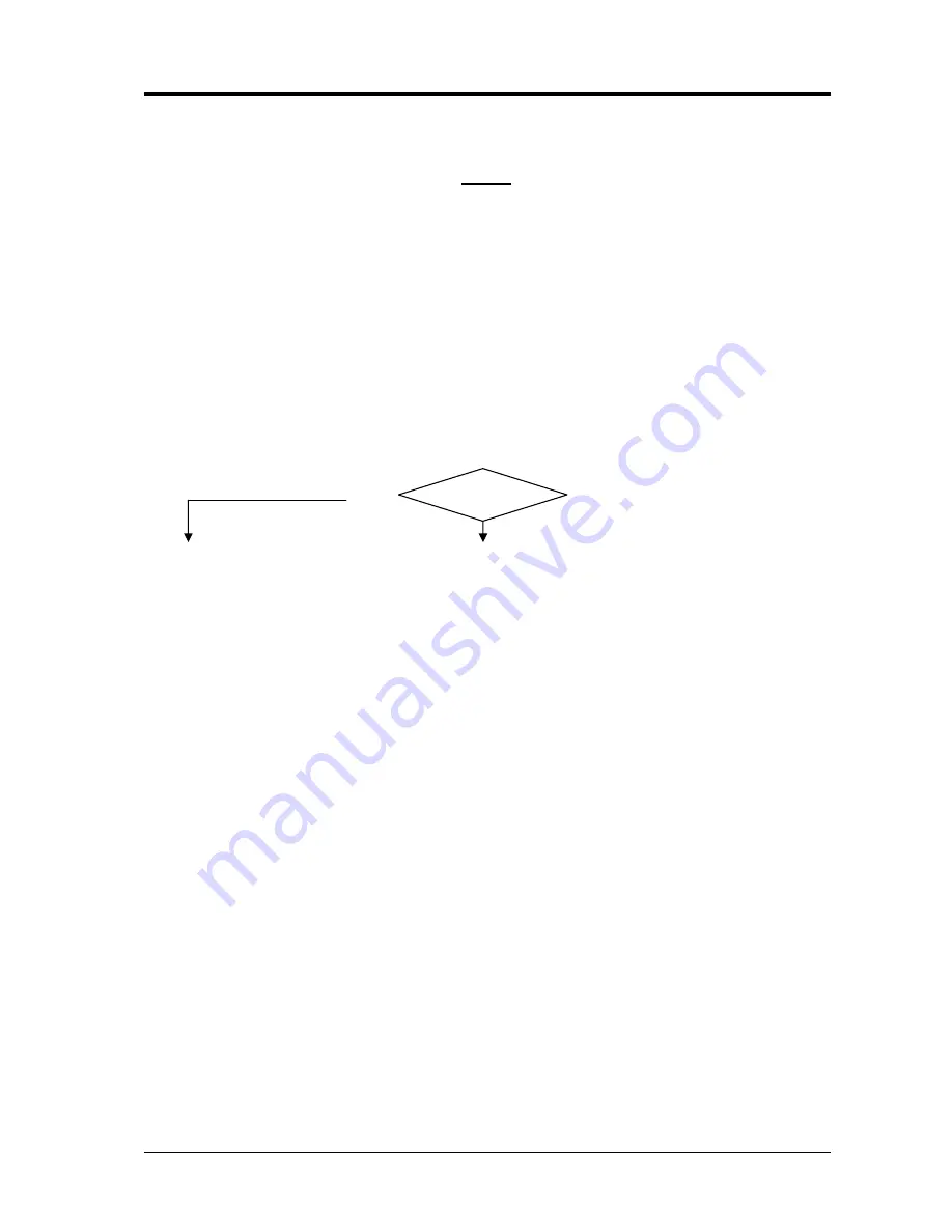
WIRE FEEDER MOTOR (403) BRAKING TEST. 

Correct? 

‰


Control board (4), connector J8 terminals 1 and 2 (gnd) = fig. 5.2.1, when the start button is 
released, with the power source open-circuit (no wire in the torch). The wire feeder motor 
stops immediately (braking time <200 msec.). 
 
 YES 
 
 NO 


If you encounter fig. 5.2.2 (the motor slows from its own inertia), the braking 
circuit on the control board (4) does not work properly, replace control board (4). 


Make sure that there are no mechanical impediments preventing the wire coil from stopping 
despite the braking action of the motor (ex.: sliding by wire feeder rollers, improperly 
adjusted roller spring). 


Replace the control board (4) and/or motor (403). 

3.302.200 

29/04/05 

Содержание MIG 4540/T

Страница 1: ...CEBORA S p A 1 BRAVO SYNERGIC POWER SOURCE art 597 SERVICE MANUAL 3 302 200 29 04 05...

Страница 2: ...operation the output voltage is not regular 16 3 3 9 In synergic mode he welding quality is not satisfactory the wire speed is not suited to the output current 17 3 3 10 Arc difficult to strike the a...

Страница 3: ...replace them with original Cebora spare parts 1 3 Safety information The safety notes provided in this manual are an integral part of those given in the Instruction Manual Therefore before working on...

Страница 4: ...ctor 51 closes which is controlled by the control board 4 based on the welding conditions set by the operator The service transformer 55 receives the supply voltage through the voltage change terminal...

Страница 5: ...downstream of the rectifier bridge 56 serves to level the welding current and its intermediate sockets allow you to maximize welding quality as the material to be welded changes The shunt 23 inserted...

Страница 6: ...and torch replace if aged or damaged Check the condition of the internal power connections and connectors on the electronic boards if you find loose connections tighten or replace the connectors 3 2...

Страница 7: ...h time the key E is pressed the leds B C and D light in sequence and display H shows the value of the function indicated by the corresponding lit led NO see 3 3 3 YES WARNING DURING THE FOLLOWING TEST...

Страница 8: ...5 Correct With voltage led I lit or thickness led L lit selected the value on display H may be changed using the switches 44 and 45 NO see 3 3 3 3 3 7 YES Use the keys E O or N to select a synergic pr...

Страница 9: ...ort circuits or isolation leaks between the various conductors and towards earth in connections between the power cable terminal board 50 contactor 51 switches 44 45 service transformer 55 fan 58 and...

Страница 10: ...orrect Terminals of fan 58 approximately 230 Vac with mains at either 230 Vac or 400 Vac with start button pressed NO YES Make sure that there are no mechanical impediments blocking the fan Check with...

Страница 11: ...ace control board 4 if necessary Make sure the power supply to the service transformer 55 is correct performing if necessary the CONTROL BOARD 4 POWER SUPPLY TEST in par 3 3 1 Replace service transfor...

Страница 12: ...o gas flows from the torch SOLENOID VALVE 12 TEST Correct Solenoid valve 12 terminals 28 Vac with torch button pressed and for as long as the button is held down plus the post gas time NO YES Check th...

Страница 13: ...e off temporarily disconnect the terminals of the wire feeder motor 403 from the connector J8 control board 4 and check the resistance between the motor terminals left free Correct value approximately...

Страница 14: ...e operation of the rectifier 56 may improve and the measurable values may become closer to those given 10 Therefore for measuring we recommend using the latter method and consider not so important the...

Страница 15: ...2 3 4 5 6 7 8 19 7 20 1 20 4 20 9 21 3 22 3 22 8 23 8 25 7 26 4 27 1 27 7 28 5 30 2 31 1 33 Correct NO YES Check the wiring between the secondary transformer 5 circuit and rectifier 56 Check the effic...

Страница 16: ...itches 44 and 45 and the voltage change terminal board 59 are intact If you find loose connections tighten them and replace any components with damaged terminals Check the efficiency of switches 44 an...

Страница 17: ...e the control panel is working properly see par 3 3 3 Replace motor control board 4 3 3 10 Arc difficult to strike the arc goes out immediately after lighting NOTE In the power sources art 957 the Sof...

Страница 18: ...tc Thus if the wire sticks to the workpiece at the end of the welding process consider the aforementioned conditions and perform the following test WIRE FEEDER MOTOR 403 BRAKING TEST Correct Control b...

Страница 19: ...guard are in good condition and properly mounted With the guard closed the contact of switch 46 must be closed If incorrectly positioned correct the position replace if defective Check on terminals 7...

Страница 20: ...motor 1 61 3065118 fan 1 Recommended spare parts Rif Code Description Q t 6 3060278 coil support 1 12 3160181 solenoid valve 1 40 5803982 handle 1 41 3060247 handle support 2 44 3190515 selector swit...

Страница 21: ...wer source art 597 see file SCHE597 pdf enclosed at the end of manual 5 2 Waveforms 5 2 1 Wire feeder motor 403 voltage during correct braking par 3 3 11 5 2 2 Wire feeder motor 403 voltage during inc...

Страница 22: ...16 Vac input timing board 62 safety circuits and start button on the torch power supply J1 3 4 signal input from flow meter on cooling unit J1 5 cooling liquid flow signal output J1 6 NU J1 7 8 start...

Страница 23: ...J4 1 power source output current signal input J4 2 shared input for power source output voltage and current detection circuits J5 NU board programming J6 NU J7 1 2 28 Vac input for control board 4 pow...

Отзывы: