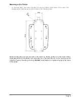
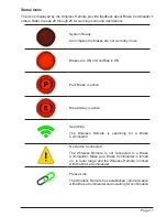
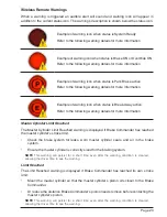
Brake Commander R2-04-0 Скачать руководство пользователя страница 19

Page 19

Stroke
After Brake Commander is installed, the master cylinder’s stroke must be entered into the 

system. To set the stroke, enter the Settings menu (by pressing the Setup button) and locate 

the Stroke parameter. Use the “ + ” (plus)  or “ - “ (minus) button to adjust the value.
Allowable range is from 10.0mm to 45.0mm. The default value is 25.4mm. 
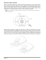
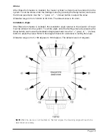
Installation Angle
After Brake Commander is installed, the installation angle relative to the direction of travel 

must be entered into the system. To set the angle, enter the Settings menu (by pressing the 

Setup button) and locate the Installation Angle parameter. Use the “ + ” (plus)  or “ - “ (minus) 

button to adjust the value. Refer to the diagram below for assistance in setting the angle.
Allowable range is from -180 degrees to 180 degrees. The default value is 0 degrees.

NOTE

 When the device is not mounted on “Normal” angles, the mounting angle will need to be 

determined accurately.

Содержание R2-04-0

Страница 1: ...USER MANUAL R2 04 0 MultiVolt 12 24V...

Страница 2: ...Page 2...

Страница 3: ...Attaching a Master Cylinder 11 Electrical Overview 11 Electrical Specifications 12 Electrical Connections 13 Auxiliary Circuit Test 13 Tail Light Circuit Test 13 Brake Light Circuit Test 14 Connecting...

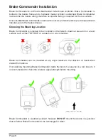
Страница 4: ...Page 4 Overview Brake Commander...

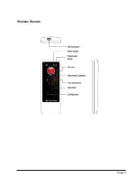
Страница 5: ...Page 5 Wireless Remote...

Страница 6: ...e system checks detect any issues the Wireless Remote will display a status icon and warning message Refer to page 17 for status icon details and pages 23 through 25 for warning messages NOTE A Low Po...

Страница 7: ...ed in the device If the Wireless Remote is lost or damaged the braking system will continue to provide braking however the minimum brake response will be significantly higher so as to act as a warning...

Страница 8: ...sure to the trailers brakes Choosing the Mounting Location Brake Commander is intended to be mounted on the trailer s draw bar area and on a level surface such as the TOP FACE of a draw bar or cross m...

Страница 9: ...dicates the size and location of the mounting holes Brake Commander can be secured to the trailer by directly bolting it to the trailer frame Alternately Brake Commander can be bolted to a sub plate t...

Страница 10: ...sket compound may be used to seal this connection NOTE The available stroke of master cylinder is required for the stroke parameter in the Wireless Remote s Setup menu When Brake Commander is powered...

Страница 11: ...ing the vehicle s lights to Parker s or Head Lights to provide power on the Tail Light Circuit NOTE When initially charging the Brake Commander 12 24v units the charge rate will begin at a reduced amo...

Страница 12: ...motorbike battery and test leads to test the wiring connection s Alternatively if you are confident that the electrical connections are correct you may use the tow vehicles standard connection as the...

Страница 13: ...R LED will turn OFF immediately when the 12V power source is removed NOTE At this stage Do Not leave the power source attached for longer than 10 20 seconds this prevents the start up routine running...

Страница 14: ...l Light Circuit Test however this time leave the 12V power source connected 1 Allow Brake Commander to charge for 2 minutes During this time a connection with the Wireless Remote will be established i...

Страница 15: ...the battery level Note If the battery indicator is RED while charging the Wireless Remote is preconditioning the battery and will automatically switch off if removed from the USB power source Turning...

Страница 16: ...or Override Button The STATUS LED on the Brake Commander will blink rapidly whenever Brake Commander is resetting the wireless network the wireless network is reset whenever there is no communication...

Страница 17: ...s are ON or OverRide is ON Park Brake is active Break Away is active Searching The Wireless Remote is searching for a Brake Commander No Device Connected The Wireless Remote is not connected to a Brak...

Страница 18: ...essing the Setup button and locate the Brake Response Reverse parameter Use the plus or minus button to adjust the value Allowable range is from 0 to 100 The default value is 20 Settings menu when Loc...

Страница 19: ...gle After Brake Commander is installed the installation angle relative to the direction of travel must be entered into the system To set the angle enter the Settings menu by pressing the Setup button...

Страница 20: ...the position in which Brake Commanders piston returns to when the brakes are released The start point can be adjusted using the plus or minus button The Brake Commander piston will jog in the desired...

Страница 21: ...sing the Wireless Remote as described above or by the Automatic Park Brake release NOTE When bleeding brakes on your trailer the Park Brake can be engaged and disengaged to pump the brakes Make sure B...

Страница 22: ...tus ON Brake Commander is ON and there are no warnings or active functions Brake Commander is ready for use Quick blink long pause The Park Brake is Active Blink pause Brake Commander is starting up o...

Страница 23: ...er Cylinder Limit Reached The Master Cylinder Limit Reached warning is displayed if Brake Commander has reached the master cylinder s stroke limit Check the brake system for leaks worn master cylinder...

Страница 24: ...r source meets the Electrical Specifications on page 11 NOTE This warning will persist for a short time even after the warning condition is cleared allowing the driver time to see the warning No Power...

Страница 25: ...master cylinder s stroke has been set correctly NOTE In the shutdown condition brake output will be maintained at the level prior to the shutdown The motor will be released from the shutdown after 5...

Страница 26: ...Page 26 NOTES...

Страница 27: ...Page 27 NOTES...

Страница 28: ...P O BOX 2107 Phone 1300 94 97 98 Bowral NSW 2576 Australia Web www brakecommander com Brake Commander S N Wireless Remote S N...

Отзывы: