4
26. Never allow anyone to stand under a suspended
load.
27. Exposed areas of capstan shafts are dangerous.
Clothing and other items may become tangled and
wrapped around the shaft when rotating. Appropriate
guarding should be installed to prevent any part of
the body or clothing from contacting the shaft
when it is rotating. Failure to provide appropriate
guarding could result in property damage, injury or
death.
WARNING: This emblem is used to warn
against hazards and unsafe practices which
could result in severe personal injury or death
if proper procedures are not followed.
CAUTION: This emblem is used to warn
against potential or unsafe practices which
could result in personal injury or product or
property damage if proper procedures are not
followed.
CAUTION
Safety information callouts used in this manual:
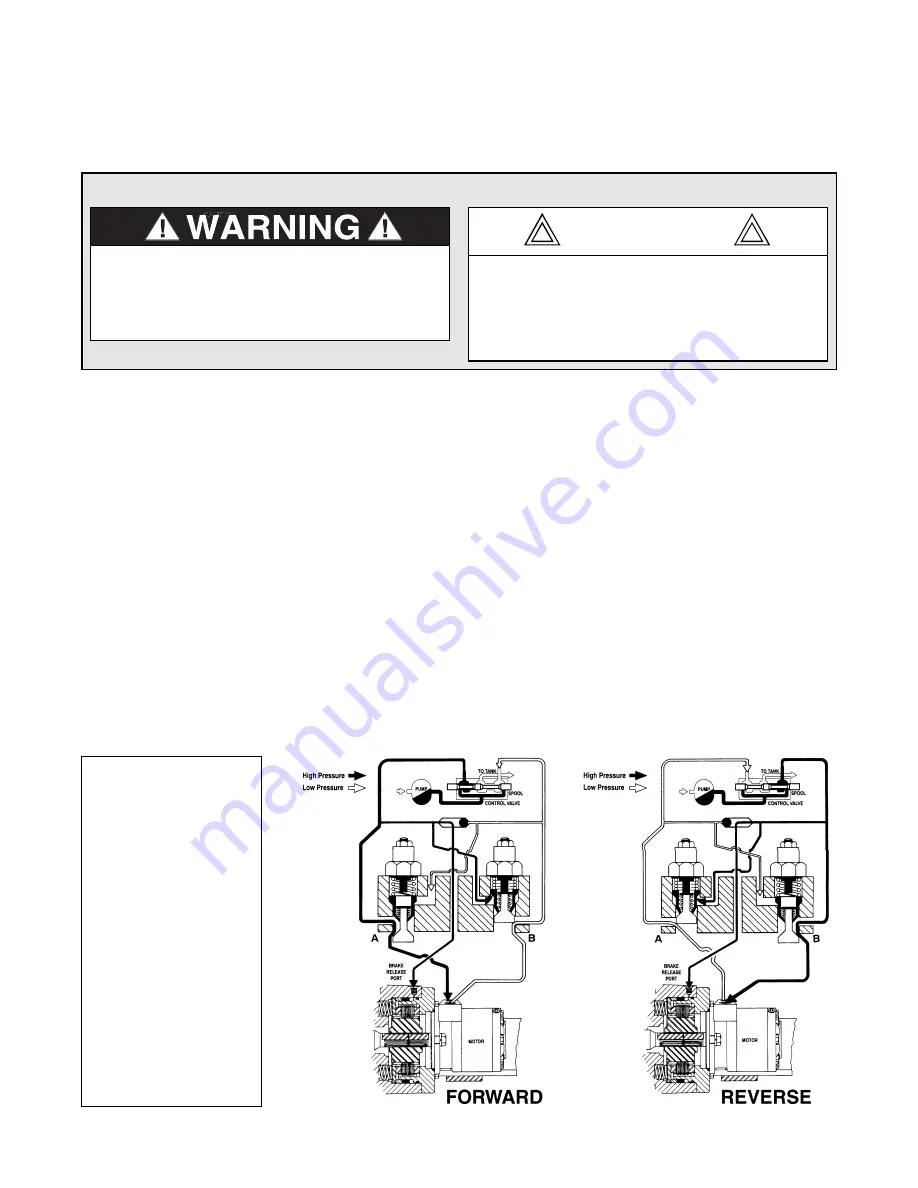
THEORY OF OPERATION
The PCD24B capstan drive is made up of the follow-
ing sub-assemblies and parts:
1. Hydraulic motor and brake valve block with
cartridges.
2. Static brake assembly.
3. Planetary gear set.
4. Output shaft and bearings.
The static brake assembly is a multiple disk pack which
is spring applied, hydraulically released, and equipped
with a solid hub coupling the motor shaft to the plane-
tary sun gear. This means that the static brake is
applied when the drive is stopped, keeping the output
shaft from rotating in either direction. Also, the motor
cannot operate the drive in either direction until the brake
has been released.
In operation, the static brake must be hydraulically
released when the drive is operated in either direction.
When the control valve handle is moved in either direc-
tion, hydraulic pressure is piloted to the brake release
piston and routed to the motor at the same time. Oil
flow out of the motor is initially blocked by one of the
counterbalance cartridges. As hydraulic pressure
increases, the static brake is released. At this time, oil
flow out of the motor is still blocked. As pressure con-
tinues to increase, the cartridge is piloted open and the
motor is allowed to turn. This sequence ensures the static
brake is completely released before any rotation occurs,
resulting in minimal wear of the friction disks in the brake
assembly. The extent to which the cartridge opens will
determine the amount of oil that can flow through it and
the speed of the output shaft. Increasing the flow of oil
to the drive will cause the pressure to rise and the open-
ing in the cartridge to enlarge, allowing more oil to flow
and increasing the speed of the output shaft. Decreasing
this flow causes the pressure to lower, decreasing the
opening in the cartridge and slowing down the output
shaft. When the control valve is returned to center and
oil flow is stopped, motor rotation stops and the static
brake is fully applied by the brake springs.
Disc brake (static parking
brake) releases at approx.
390 psi (2,690 kPa) at no
load.
Dual cartridge counter-
balance valve opens at
aprox. 960 psi (6,620 kPa) at
15 gmp (57 Lpm).
Dual cartridge counter-
balance valve opens at
approx. 1,580 psi (10,890
kPa) at 30 gpm (114 Lpm).
NOTE: Pressures shown
above are
Δ
P across the
motor.


