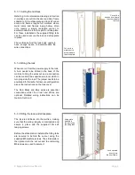
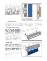
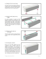
background image

© Magna Electronics Pte Ltd.  


             Page 8 

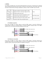
6. WIRING  


The COBALT is supplied with a 7-way wire loom that plugs directly into the lock. The wires are colour coded with 
three being essential connections and four optional. Control of the lock is achieved by using the three power wires, 
whilst door and bolt position monitoring are available when desired. Connect the COBALT as per the chart: 


RED 

POS 

Positive connection to DC power supply (12

–24V) 

Power 

BLACK 

NEG 

Negative connection to DC power supply (12

–24V) 

BLUE 

CTRL 

Switched positive control input 

VIOLET 

NO 

Normally open contact of the bolt position monitor 

Bolt Position Switch  

VIOLET 

COM 

Common contact of the bolt position monitor 

WHITE 

NO 

Normally open contact of the door position monitor 

Door Position Switch 

WHITE 

COM 

Common contact of the door position monitor 


6.1 Fail Safe Connection 


When  wiring  the  COBALT,  the  positive  voltage  is  connected  to  RED,  negative  is  connected  to  BLACK  and  a 
switched  positive  voltage  wire  connected  to  BLUE.  In  Fail  Safe  configuration  applying  voltage  to  the  COBALT 
signals it to lock. The lock signal in Fail Safe configuration is active high.  


6.2 Fail Secure Connection 


When  wiring  the  COBALT,  the  positive  voltage  is  connected  to  RED,  negative  is  connected  to  BLACK  and  a 
switched  positive voltage  wire  connected  to  BLUE.  In  Fail  Secure  configuration  applying voltage  to  the  COBALT 
signals it to unlock. The lock signal in Fail Secure configuration is active low.  


DC Power Supply 

NO 

NC 

Bolt Position Switch (user monitor) 

Door Position Switch (user monitor) 

WHITE 

WHITE 

VIOLET 

VIOLET 

BLUE 

BLACK 

RED 

Lock 
Wire 
Loom 

WHITE 

WHITE 

VIOLET 

VIOLET 

BLUE 

BLACK 

RED 

NC 

NO 

Bolt Position Switch (user monitor) 

Door Position Switch (user monitor) 

Lock 
Wire 
Loom 

DC Power Supply 

Содержание Cobalt YD30

Страница 1: ...YD30 COBALT INSTALLATION AND OPERATING INSTRUCTIONS ...

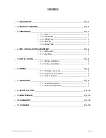
Страница 2: ... o 4 1 Mechanical o 4 2 Electrical 5 INSTALLATION o 5 1 Mortise Installation o 5 2 Surface installation 6 WIRING o 6 1 Fail Safe connection o 6 2 Fail Secure connection o 6 3 Jumper position 7 OPERATION o 7 1 Fail Safe Operation o 7 2 Fail Secure Operation 8 SPECIFICATIONS 9 MAINTENANCE 10 WARRANTY 11 UPGRADE Pg 2 Pg 2 Pg 3 3 3 3 3 3 Pg 4 4 4 Pg 4 4 6 Pg 8 8 8 9 Pg 9 9 9 Pg 10 Pg 10 Pg 10 Pg 10 ...

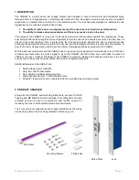
Страница 3: ...tes A door that is 8mm off alignment in either direction 16mm total window will be secured with the COBALT With the door secured and locked the COBALT can be given an unlock signal and it will instantly unlock If the door is loaded pre load when the unlock signal is given the COBALT will still unlock even with loads in excess of 100Kg on the door Critically the ability of the COBALT to instantly r...

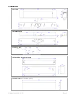
Страница 4: ... Magna Electronics Pte Ltd Page 3 3 DIMENSIONS 3 1 Lock 3 2 Strike Plate 3 3 Fitting Tab 3 4 Housing Available separately 3 5 Dress Plate Available separately ...

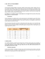
Страница 5: ...position feedback These optional connections can be integrated into access control or alarm systems to provide full monitoring The correct gauge of wire needs to be chosen as voltage drop across the power wires and can limit the locks operation For all the remaining connections a lower gauge wire can be used as these are only signal wires The following chart shows the maximum distance that the pow...

Страница 6: ...made to the supplied wire loom which in turn plugs into the lock The jumper needs to be positioned for fail safe fail secure configuration as per the instructions on the lock cover The Red Black and Blue wires are essential connections whilst the Violet and White are optional Detailed wiring instructions can be found in Section 6 5 1 3 Fitting the lock and strike plate The lock is slid back into t...

Страница 7: ...g determine exactly where the wiring will enter the housing and drill one or two 8mm holes through the housing wall Ensure the holes are on the housing face that goes against the wooden frame Push the supplied grommet s into the drilled hole s The two 10G Hex head self tapping screws supplied with the housing can then be screwed into the wood but not tightened The two keyhole shaped cut outs in th...

Страница 8: ...ass to give a clean finish The protective coating on the dress plate can be removed once it is in place 5 2 5 Fitting the strike plate into the housing The strike plate is placed into the housing and secured in place with the supplied M5 machine screws 5 2 6 Checking the operation With the lock and strike installed and wiring complete the door is closed to check the alignment and operation The key...

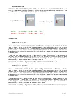
Страница 9: ...Common contact of the door position monitor 6 1 Fail Safe Connection When wiring the COBALT the positive voltage is connected to RED negative is connected to BLACK and a switched positive voltage wire connected to BLUE In Fail Safe configuration applying voltage to the COBALT signals it to lock The lock signal in Fail Safe configuration is active high 6 2 Fail Secure Connection When wiring the COB...

Страница 10: ...g as the door is open but will instantly re lock when voltage is applied to the BLUE wire and the door is closed In the event of a power failure voltage is removed from the BLUE wire and the COBALT unlocks 7 2 Fail Secure Operation Assume the lock is installed and wired the door is open and voltage is removed from the BLUE wire As the door closes the COBALT senses the door approaching and activate...

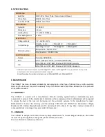
Страница 11: ...mA 24VDC 9 MAINTENANCE The COBALT has been lubricated at assembly and applying any other type of lubricant may void the warranty Removing the lock cover may void the warranty A dry cloth can be used to polish the stainless steel face plate and strike plate as required 10 WARRANTY The COBALT is covered with a manufacturers 12month warranty against faulty or malfunctioning parts components or produc...

Страница 12: ... Magna Electronics Pte Ltd Page 11 NOTES ...

Отзывы: