background image

USB3.0


Fixture


Board


User’s


Manual


Page


7


FAE2009U3EX_02                                                 ©2009 Bplus Technology 


Current test method with load 

I

1


So the Load current 

I

load

=

I

1

-

I

0

=30.88mA-0=30.88mA 

2. 

V

out

=3.3V, current test method: 


Current test method without load 

I


Содержание U3EX

Страница 1: ...USB3 0 Fixture Board User s Manual Model U3EX FAE2009U3EX_02 Sep 2009 Bplus Technology Co Ltd 5F No 63 Zhou Tzyy St Nei Hu Taipei Taiwan 886 2 77210550 TEL 866 2 87974200 FAX http www Bplus com tw ...

Страница 2: ...USB3 0 Fixture Board User s Manual Page 1 FAE2009U3EX_02 2009 Bplus Technology CONTENTS Introduction 2 Interface 2 Function 3 Schematic profile 3 Application note 4 Caution 9 Maintenance 9 ...

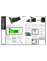
Страница 3: ...ulti functions of voltage switch voltage test and current test It s especially designed to save valuable labor and time in the production environment The USB Fixture is constructed of high quality components for years of trouble free service 2 0 Interface USB 3 0 Fixture Board as shown Figure 1 USB3 0 Fixture Board heads Figure 2 USB3 0 Fixture Board back ...

Страница 4: ...t Voltage 5v to 5v 3 3v z Voltage can be tested conveniently and directly z Current can be tested conveniently and directly z External power supply support 4 0 Schematic profile 1 IC1 can work as short and over load protection When external load current is larger than 500mA or short output it will perform protection function Meanwhile LED D3 R will show on for warning function 2 IC2 is a voltage c...

Страница 5: ...ifferent Voltage switch Set Jumper Cap on JP1 1 2 position IC1 can work normally Set Jumper Cap on JP2 1 2 position IC2 cannot work Meanwhile LED D2 G will show on and output voltage shows 5V Set Jumper Cap on JP1 1 2 position IC1 can work normally Set Jumper Cap on JP2 2 3 position IC2 can work normally Meanwhile LED D1 Y and LED D2 G will show on Output voltage shows 3 3V ...

Страница 6: ...ltage shows 5V Set Jumper Cap on JP1 2 3 position IC1 cannot work Set Jumper Cap on JP2 2 3 position IC2 can work normally Meanwhile output voltage shows 3 3v z Voltage test TP2 is a test point for input voltage 5V TP3 is a test point for output voltage Vout Input voltage can be obtained by measuring TP2 and TP4 TP1 and output voltage can be obtained by measuring TP3 and TP4 TP1 Vout 5V test metho...

Страница 7: ...USB3 0 Fixture Board User s Manual Page 6 FAE2009U3EX_02 2009 Bplus Technology Vout 3 3V test method z Current test 1 Vout 5V current test method Current test method without load I0 ...

Страница 8: ... Board User s Manual Page 7 FAE2009U3EX_02 2009 Bplus Technology Current test method with load I1 So the Load current Iload I1 I0 30 88mA 0 30 88mA 2 Vout 3 3V current test method Current test method without load I0 ...

Страница 9: ...load I1 So the Load current Iload I1 I0 43 6mA 13 0mA 30 6mA z External power supply For USB special voltage supply need the user can choose external power to replace USB power supply Before using the user must remove Jumper Cap on JP1 and JP2 position and ensure TP3 connecting with VOUT TP4 TP1 with GND ...

Страница 10: ...aution z All products specifications are subject to change without notice z Bplus Technology reserves the right to modify the products in its line during the course of the year 7 0 Maintenance There is no guarantee for incorrect operation Please contact the distributer for more details ...

Отзывы: