
32
PowerPro HP300 Series User Manual
4.
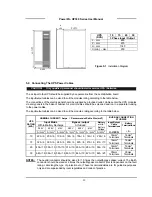
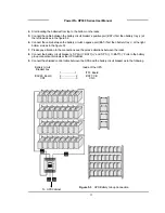
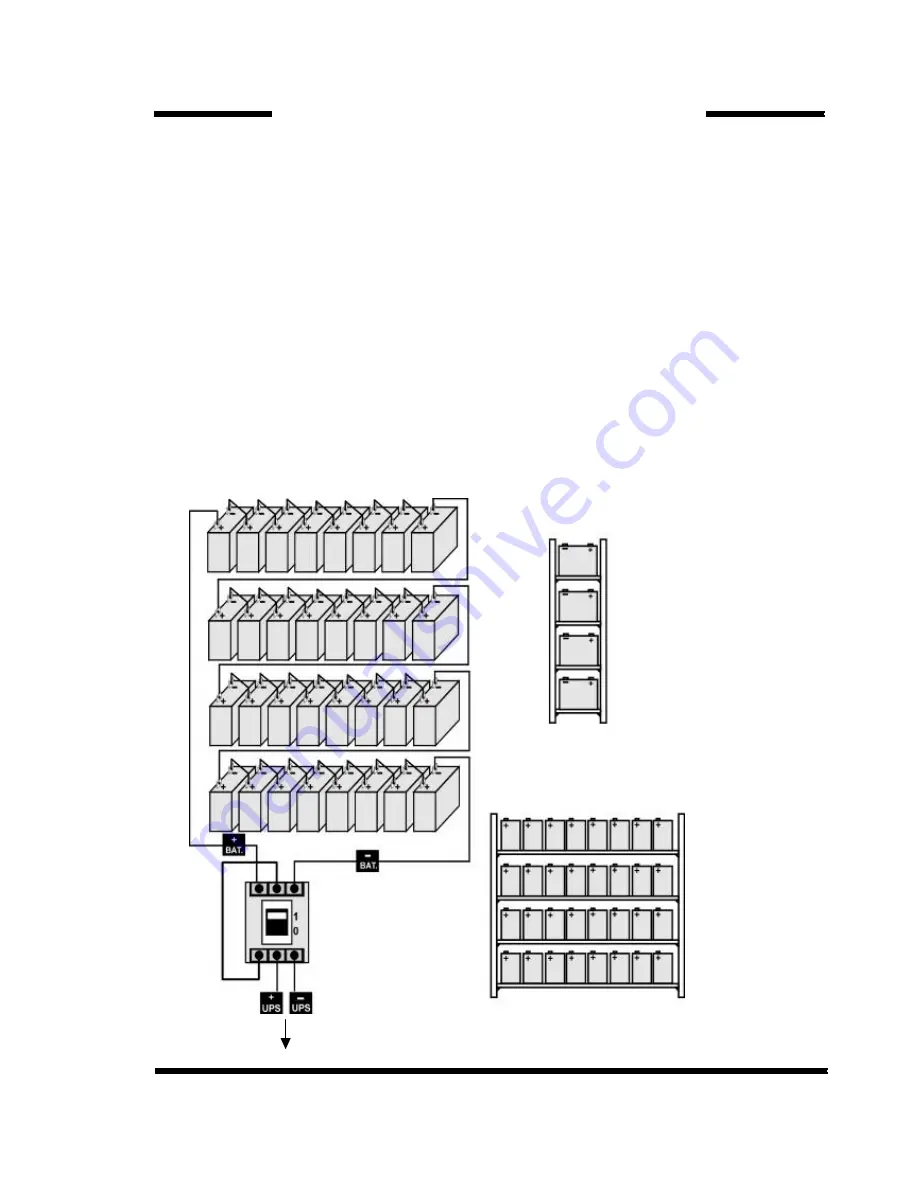
Start locating the batteries from top to the bottom on the racks.
5.
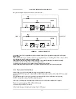
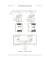
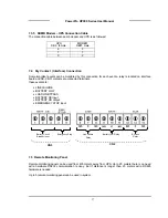
Connect the cable between the battery circuit breaker’s positive port (BAT+) first then battery tray (+) at
the left topside as in the figure 5-3
6.
Connect the cable between the battery circuit’s negative port (BAT-) first then battery tray (-) at the right
bottom side as in the figure 5-3
7.
Please pay attention to the connections and the poles’s directions between the racks.
8.
Connect the battery circuit breaker’s “UPS(+)
⇒
BATT(+)” and “UPS (-)
⇒
BATT(-)” Ports to the battery
group connection terminals at the UPS cabinet.
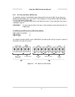
9.
Connect the shielded control cable between the UPS and the battery circuit breaker as in the following.
Battery circuit
Inside of the UPS
Breaker box
1.....................1 ITF3 Board
BAC60 Board
2.....................2
BATT. CB
CN1
3.....................3
CN3
Figure 5-3
UPS Battery Group Connection
To UPS Cabinet