2
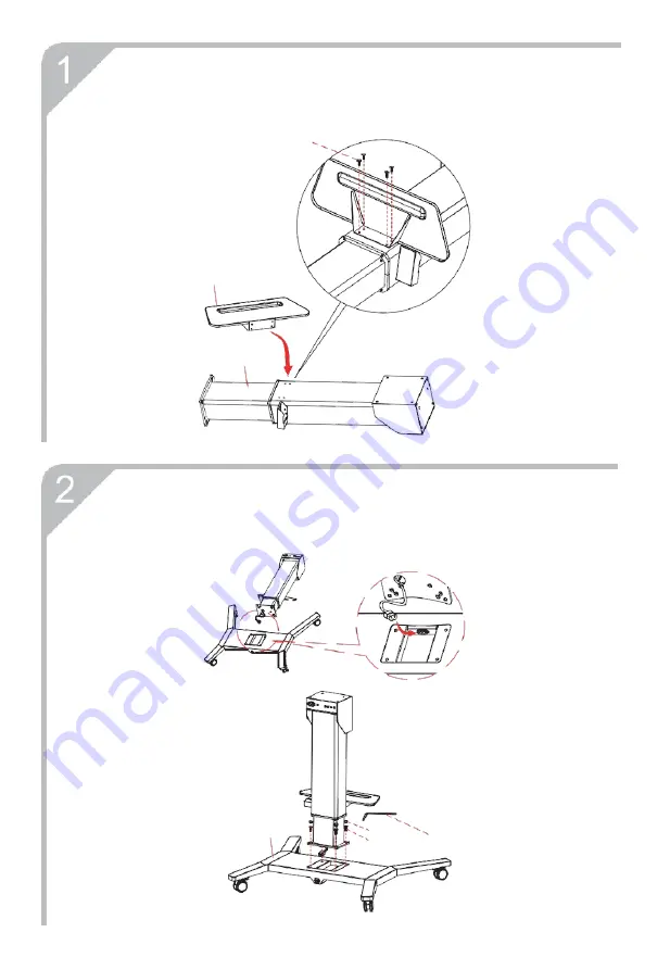
Step2: Connect the power cable between the lifting column B and thebase A, install the lifting column and tighten the screws (figure 2).
A
⑤
①
⑥
figure 2
Step1: The shelf D is fixed with the lifting column B (figure 1).
④
D
B
figure 1
Страница 1: ...perly and safely please follow the contents of the Installation and Operation Manual to install It is suggested that this Electric Stand applies to the 55 75 inch intelligent panel This stand can carr...
Страница 2: ...er Cable 1pcs H USB Cable 1pcs I AC Power transfer Cable 1pcs Hexagon socket countersunk head screws KM10 25 4pcs Cross recessed pocket hexagon head screw M8 20 4pcs Cross recessed pocket hexagon head...
Страница 3: ...nnect the power cable between the lifting column B and the base A install the lifting column and tighten the screws figure 2 A figure 2 Step1 The shelf D is fixed with the lifting column B figure 1 D...
Страница 4: ...ing hole K 1 or K 8 15 18 or Recommended mounting hole Panel size K all 55 K 8 18 65 K 15 18 70 K 18 75 The specific installation holes can be adjusted according to the actual needs refer to the insta...
Страница 5: ...trol pad and the AC power cable should be connected to the Electric Stand and connected to the power supply figure 6 F figure 6 G 5 Step5 Hang the Interactive Flat Panel to the Electric Stand by Wall...
Страница 6: ...5 8 Step8 Done as shown in figure 8 figure 8 7 Step7 Plugging the AC Power transfe Cable and the USB Cable in user can interact with the Interactive Flat Panel figure 7 H I figure 7...