background image

ENGLISH-6

INSTALLATION

INSTALLATION

Installation of the Projector and Screen

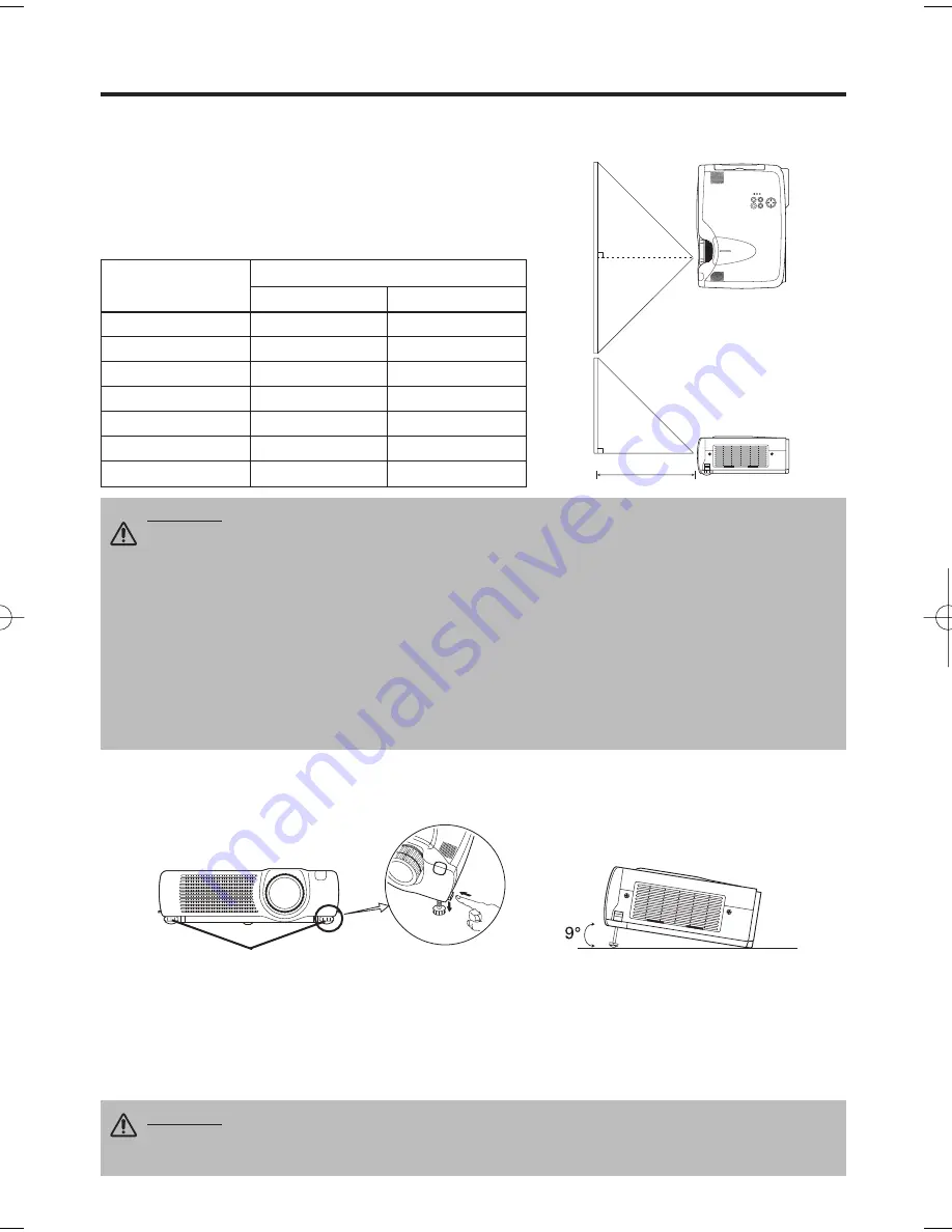
Refer to the drawing and table below for determining the screen size and projection distance.

Top View

Side View

Screen size
[inches (m)]

a

[inches (m)]

Min.

Max.

40  (1.0)

62  (1.6)

82  (2.1)

60  (1.5)

94  (2.4)

123  (3.1)

80  (2.0)

127  (3.2)

164  (4.2)

100  (2.5)

160  (4.1)

205  (5.2)

120  (3.0)

192  (4.9)

246  (6.3)

150  (3.8)

241  (6.1)

308  (7.8)

200  (5.0)

323  (8.2)

411 (10.4)

Angle Adjustment

Use the foot adjusters on the bottom of the projector to adjust the projection angle. It is variable
within 0˚ to 9˚ approximately.

1. Lift up the front side of the projector, and pressing the foot adjuster button, adjust the projection

angle.

2. Release the button to lock at the desired angle.
3. 

Use

 the foot adjusters for fine adjustment. Do not force the adjuster screw

s

. This

could damage the adjusters or cause the lock to fail.

The projection distances shown in the table below are for
full size (1024 x 768 dots).

a

: Distance from the projector to the screen. (±10%)

Table 1. Installation Reference

a

CAUTION • Install the projector in a suitable environment according to instructions of
the accompanying manual “SAFETY INSTRUCTIONS” and this manual.
• When you fix this unit with a metal tool and the like, you must connect it with ground

wire; otherwise, fire or electric shock can result.
Connect the ground terminal of AC inlet of this unit with the ground terminal provided at the
building using an optional three-core power-supply cord.
• Please basically use liquid crystal projector at the horizontal position. If you use liquid
crystal projector by the lens up position, the lens down position and the side up position, this
may cause the heat inside to build up and cause damage. Be especially careful

 not to install it 

with ventilation holes blocked.
• Do not install LCD projector in smoke effected environment. Smoke residue may buildup
on critical parts (i.e.LCD panel, Lens Assy etc.).

CAUTION • Do not release the foot adjuster button unless the projector is being held;
otherwise, the projector could overturn or fingers could get caught and cause

personal injury.

Foot Adjusters

Press the foot
adjuster button

01CP-775i  02.1.29 10:25 AM  ページ 6

Содержание CP-775i

Страница 1: ...entamente il manuale d sitruzioni in modo tale da poter comprendere quanto riportato ai fini di un corretto utilizzo del proiettore MANUAL DE USUARIO Lea cuidadosamente este manual del usuario para po...

Страница 2: ...Message 20 Table 10 Indicators Message 21 Table 11 Symptom 22 Table 12 Specifications 23 For TECHNICAL and REGULATORY NOTICE see the end of this manual The information in this manual is subject to cha...

Страница 3: ...iese Bedienungsanleitung zugunsten der korrekten Bedienung aufmerksam MANUEL D UTILISATION Nous vous recommandons de lire attentivement ce manuel pour bien assimiler le fonctionnement de l appareil MA...

Страница 4: ...r Filter and Intake for the Cooling Fan INPUT Button LAMP Indicator TEMP Indicator POWER Indicator RESET Button MENU Button Ventilation Openings exhaust REAR RIGHT VIEW OF THE PROJECTOR Terminal Panel...

Страница 5: ...Button MOUSE RIGHT Button Used to click the right mouse button RESET Button Used to click the right mouse button FREEZE Button MUTE Button PinP Button KEYSTONE Button VOLUME Button These functions wor...

Страница 6: ...Use only the specified batteries with this remote control transmitter Also do not mix new and old batteries This could cause battery cracking or leakage which could result in fire or personal injury...

Страница 7: ...to the screen 10 Table 1 Installation Reference a CAUTION Install the projector in a suitable environment according to instructions of the accompanying manual SAFETY INSTRUCTIONS and this manual When...

Страница 8: ...l devices to be connected except for the USB cable The cables may have to be used with the core set to the projector side Use the cables which are included with the projector or specified Cabling Refe...

Страница 9: ...ay is a system configured with peripheral equipment including a computer display and an operating system This projector is recognized as a plug play monitor Use the standard display drivers Plug play...

Страница 10: ...the POWER indicator is blinking 2 The system assumes the Standby mode when cooling is complete and the POWER indicator ceases blinking and changes to orange Check that the indicator is orange and set...

Страница 11: ...NIFY mode with a video signal is input After approximately 10 seconds of inactivity the icon is extinguished and the POSITION mode is cleared automatically and buttons may operate as the mouse control...

Страница 12: ...U SELECT Select Menu Type Press the MENU SELECT button Allows the user to select the normal menu or the single menu Only the selected item is displayed on the single menu and other items are displayed...

Страница 13: ...I VIDEO S VIDEO COMPONENT BRIGHT Adjustment Dark Light CONTRAST Adjustment Weak Strong V POSIT Adjustment Down Up H POSIT Adjustment Left Right H PHASE Adjustment Left Right Adjust to eliminate flicke...

Страница 14: ...menu This operation requires approximately 10 seconds It may not function correctly with some input signals Pressing the AUTO button in this case may correct this problem This function is the same as...

Страница 15: ...fixed screen is displayed TURN OFF displays the blue screen When MyScreen or ORIGINAL is selected the screen is going to the black after several minutes MyScreen Set MyScreen Mode Select the EXECUTE...

Страница 16: ...ear AUTO OFF Select STOP 0 min with the button When STOP is selected the system does not enter the standby mode even if no signal is received SYNC ON G SYNC ON G Valid Select TURN ON with the button S...

Страница 17: ...al is input My Screen is a mode that the customer customized screen is displayed This is the blue screen at the factory setting Refer to the description of MyScreen below ORIGINAL is a mode that the f...

Страница 18: ...mperature Before replacing the lamp switch power OFF wait approximately 20 minutes and switch power ON again If the LAMP indicator is still red replace the lamp NOTE WARNING For disposal of used lamp...

Страница 19: ...he Lamp Timer Reset the lamp timer after replacing the lamp When the lamp has been replaced after the LAMP indicator is red or the CHANGE THE LAMP message is displayed complete the following operation...

Страница 20: ...h CAUTION Switch power OFF and remove the power cord from the power outlet before beginning maintenance work Please read the separate SAFETY INSTRUCTIONS thoroughly to ensure that maintenance is perfo...

Страница 21: ...set the lamp timer after replacing the lamp CHANGE THE LAMP AFTER REPLACING LAMP RESET THE LAMP TIME THE POWER WILL TURN OFF AFTER 0 hr The usage time of lamp is about to reach Power will be switched...

Страница 22: ...ks Lights red Blinks red Turns off Lamp or lamp cover is not found or hasn t been fitted in correctly Switch power OFF and wait for 45 minutes until the equipment cools Check fitting of the lamp and l...

Страница 23: ...resent but no audio The projector is not correctly connected Connect correctly 7 8 The volume is set to minimum Press VOLUME on the remote control or display the menu screen and adjust the volume 11 1...

Страница 24: ...DC 150 1200 mV AC 1 56 Vp p TTL Level Positive Negative AUDIO IN RGB1 200mVrms 50 k max 3 0Vp p Stereo mini jack DVI RGB2 Video signal input VIDEO IN 1 0Vp p 75 terminator RCA jack S VIDEO IN Brightne...

Страница 25: ...Product WARRANTY LIMITATION AND EXCLUSION BOXLIGHT CORPORATION shall have no further obligation under the foregoing limited warranty if the Product has been damaged due to abuse misuse neglect acciden...

Страница 26: ...Printed in Japan QR52531...

Отзывы: