Copyright 2010, Bottlehead Corporation
Crack Manual
A guide to constructing the
Crack Output Transformer-Less tube headphone amplifier kit
Revised December 17, 2013
Страница 1: ...Copyright 2010 Bottlehead Corporation Crack Manual A guide to constructing the Crack Output Transformer Less tube headphone amplifier kit Revised December 17 2013...
Страница 2: ...Octal socket Nine pin miniature socket 13 Power transformer 14 Competed hardware layout 15 PART TWO CHASSIS WIRING 16 AC ground buss AC mains and power switch wiring 17 Twisted pair wiring Heater wir...
Страница 3: ...gh voltages becomes terribly im portant With the near demise of commercial tube audio gear in the late 60 s and the similar decline of kit building in the late 70 s safe test and construction techniqu...
Страница 4: ...ath to ground that s where the juice will go homes Right through you The rubber soles will insulate you from ground Another classic path to electrocution is from one hand to the other If you grab the...
Страница 5: ...ng when working on a microwave oven Suffice it to say they cut his body away from the still smoldering equipment an hour later Also it is a very good practice to only work on high voltage equipment wh...
Страница 6: ...s The Crack Output Transformer Less OTL headphone amplifier has been designed as a relatively simple highly cost effective great sounding headphone amp kit for higher impedance headphones 100 ohms or...
Страница 7: ...7 Bottlehead Crack Output Transfomer Less Headphone Amplifier 100VDC 90VDC 22K1 1 5VDC 100VDC 170VDC...
Страница 8: ...hird hand tool can be useful for situations where you need support the parts you are working on while keeping both hands free to solder Solder we recommend standard 60 40 or 63 37 tin lead solder as t...
Страница 9: ...red one black 1 rocker switch 1 0 5A fuse 1 IEC power entry fuse holder 1 fuse cover 1 knob 1 headphone jack 4 rubber feet 4 8 32x1 3 4 screws 4 nylon shoulder washers 4 8 fiber shoulder washers 4 8...
Страница 10: ...ground under here Terminal strip under here Terminal strip under here Stereo Headphone Jack Crack chassis plate top side prototype chassis shown the graining on your chassis plate will be the proper h...
Страница 11: ...rge rectangular hole at the rear of the chassis Be sure to get the power cord pins oriented to the inside of the chassis and the fuse holder to the outside as shown Next snap the power switch into the...
Страница 12: ...tentiometer shaft from the underside into the hole in the front left of the chassis Locate the indexing pin on the pot in the small indexing hole to the right of the shaft hole This keeps the potentio...
Страница 13: ...d insert another 4 40 x 1 4 screw in the rear octal socket mounting screw hole from the top side Tighten the rear screw down into the nut in the bracket flange then finish tightening the front screw N...
Страница 14: ...oles The terminals numbered 1 5 should be to the rear of the chassis and the terminals numbered 6 10 should be to the front Set a star lock washer on each hole on top of the transformer and carefully...
Страница 15: ...e shown above to iden tify connection points It is recommended that you transcribe the terminal numbering scheme shown here onto the chassis plate with a fine tipped marker to ease assembly 6 7 8 9 10...
Страница 16: ...cool to a dull finish A cold joint will not function structurally nor will it conduct properly Reheat any cold joints applying a small additional amount of solder and make sure that it cools to the p...
Страница 17: ...al wire to one end of the power transformer primary and to connect the live wire to a fuse which is then connected to a power switch which then connects to the other end of the power transformer prima...
Страница 18: ...nning the drill will spin the wires into a very even twisted pair The theoretical optimum is three turns per inch The wire will shorten as it is twisted Make sure that the finished length of the twist...
Страница 19: ...ck wire to B7U At the uneven end route the wires under the terminal strip behind the nine pin socket Attach and solder the black wire to A9 Insert the red wire end through A5 and then A4 and solder bo...
Страница 20: ...5mm and insert it through the left RCA jack ground tab and then attach it to the right RCA ground tab Solder the wire to each ground tab Strip one end of the red wire back 1 4 6mm and solder it into t...
Страница 21: ...25mm from free end of the red wire Strip 1 4 6mm of insulation from end and attach the bare end through the outboard potentiometer terminal farthest from the chassis plate Solder Trim 1 2 12mm from f...
Страница 22: ...chassis plate Attach the other end to terminal 3L but don t solder Cut a 2 1 4 56mm piece of black wire and strip both ends 1 4 6mm Attach one end to the center terminal of the nine pin tube socket A...
Страница 23: ...of one LED to the center terminal of the nine pin socket A Don t solder Attach the other end to A3 and solder Attach the silver banded end of the second LED to the center terminal of socket A and sol...
Страница 24: ...piece of white wire Strip both ends 1 4 6mm Attach and solder one end to 5L Attach and solder the other end to B4 Cut a 4 100mm piece of red wire Strip both ends 1 4 6mm Attach and solder one end to 1...
Страница 25: ...e Load Resistors These resistors create loads for the plates of the driver triodes Attach one end of an 22 1K ohm 1W resistor to 1U Attach the other end to 2U Solder 1U Attach one end of an 22 1K ohm...
Страница 26: ...transformer terminal 7 At the other end of the twisted pair attach the red wire to power transformer terminal 9 and the black wire to power transformer terminal 10 Cut a 1 1 2 37mm piece of black wire...
Страница 27: ...12mm from the rectifier body Line the rectifier body up over the first one on the same side of terminal strip with the black end attached and soldered to terminal 18L and the banded end attached to te...
Страница 28: ...ead into 15L Solder 15L Trim excess leads Cut piece of black wire 3 12 87mm long and strip both ends back 1 4 6mm Attach one end to 20U Attach the other end to 14U Attach one end of a second 270 ohm 5...
Страница 29: ...s 1 4 6mm Attach one end to terminal 12L and solder Attach the other end to the inboard terminal of the headphone jack that is closest to the chassis plate and solder Cut a 4 100mm piece of red wire S...
Страница 30: ...capacitor at 90 degrees Insert the lug by the striped side of the capacitor into terminal 14U Insert the non striped side lead into terminal 15U Double check orientation and solder Leave the lugs stra...
Страница 31: ...ther end to terminal 2L Cut a piece of red wire 2 50mm long and strip both ends 1 4 6mm Attach one end to terminal 2L and solder Attach the other end to terminal 4L and solder Also solder 2U and 4U an...
Страница 32: ...terminal7L Insert the other free resistor lead through terminal 9L Solder 3U 7L 9L and trim the excess leads Cut a 1 1 2 37mm red wire and strip both ends 1 4 Attach one end to terminal 9U and attach...
Страница 33: ...6L and solder Attach the other end to inboard Ring terminal of the TRS phone jack Cut a 5 1 2 137mm white wire and strip both ends 1 4 Attach one end to terminal 10L and solder Route the wire around...
Страница 34: ...terminals and trim excess leads Output capacitor installation Attach the striped side lead of a 100uF 160V electrolytic capacitor to terminal 6U Attach the non striped side lead to terminal 7U Double...
Страница 35: ...g they should not be touching Neatness counts It may help to have someone else look over your work too Designer Paul Joppa says having someone else check your work will reduce the possibility of a mis...
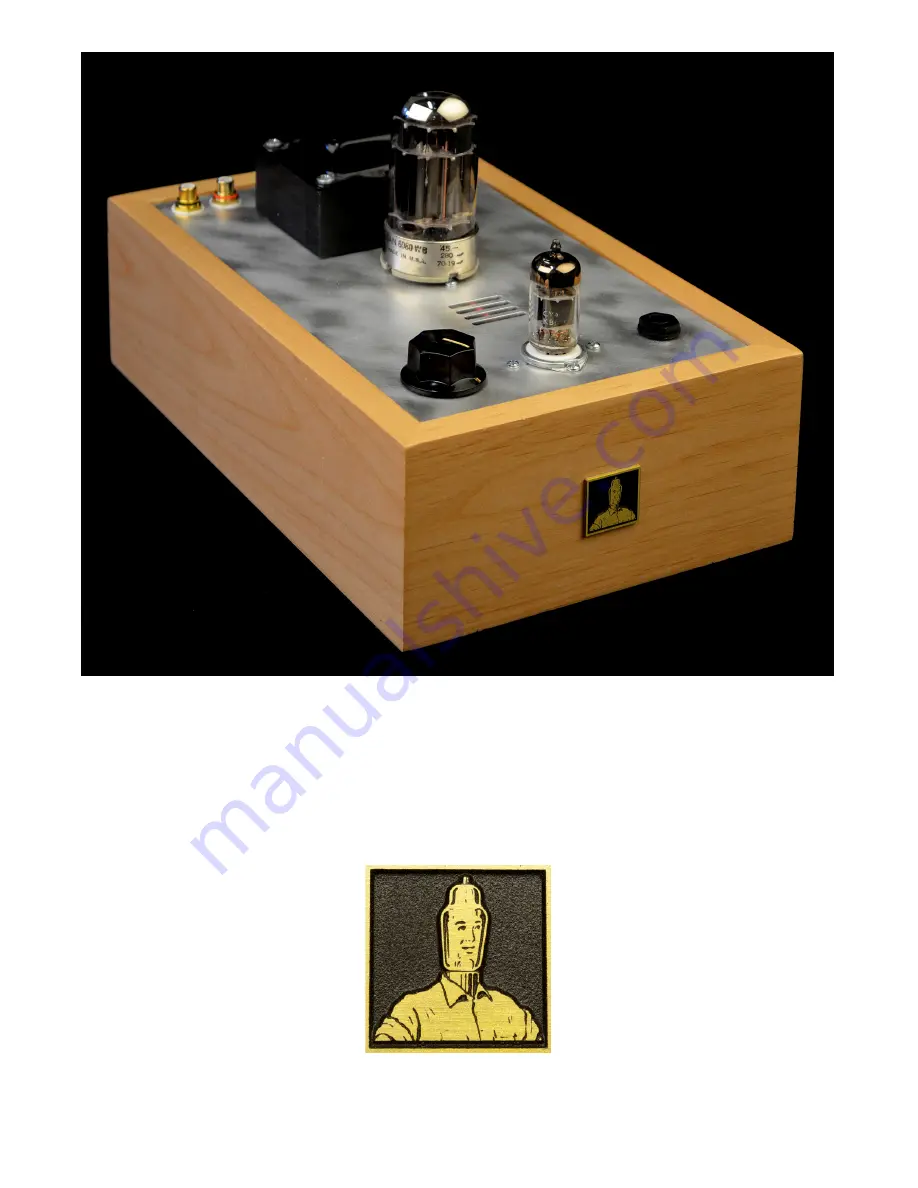
Страница 36: ...36 The completed Crack output transformerless tube headphone amplifier...
Страница 37: ...They should read roughly like this Note that the term K denotes x1000 and the term denotes ohms so 1K equals 1000 ohms 1Meg equals 1 000 000 ohms The values signified with a are going to vary from oh...
Страница 38: ...e more time Correct mis wires replace the fuse and try again If the tube filaments glow properly wait at least thirty seconds and then CAREFULLY measure voltages using the positive lead typically red...
Страница 39: ...important Power the amp down and wait for 5 minutes With the red probe now touching either the Tip or Ring terminal on the headphone TRS jack switch the amplifier on and monitor the voltage of the tip...
Страница 40: ...your sys tem It s making you crazy and you re wondering how you ever talked yourself into the idea that you could build your own gear Rule number ONE Break the system into its component parts I cannot...
Страница 41: ...through the check out voltage measurements for the channel in question Better yet re measure all your volt ages Log this info so that if you need to call us for advice we have some info to work with L...
Страница 42: ...g isn t getting voltage or it isn t getting signal Before you dive in to tear things apart check the obvious are your speaker cables hooked up properly Interconnects Is every thing switched on We see...
Страница 43: ......