


3. Push the panel mechanism back
into the housing so it is not protruding.
To do so, push the BOTTOM EDGE
down straight into the unit – do not
lift it!
(Figure 7)
.
4. Immediately place the front panel
in its protective case for safe and
clean storage
(Figure 8)
.
EON
EON
SCAN
EON
CONTENTS
MR1600W • MR1600S User’s Manual - page 1
U S E R ’ S M A N U A L
General and Tuner Controls
MR1600W • MR1600S User’s Manual - page 10
MR1600W • MR1600S User’s Manual - page 11
Wiring diagram
MR1600W • MR1600S User’
s Manual - page 18
T
r
oubleshooting
MR1600W • MR1600S User’
s Manual - page 19
Specifications
MR1600W • MR1600S User’
s Manual - page 20
MR1600W • MR1600S User’s Manual - page 4
MR1600W • MR1600S User’s Manual - page 5
Removing the head unit
Remote Control
MR1600W • MR1600S User’s Manual - page 14
General and Tuner Controls, continued
MR1600W • MR1600S User’s Manual - page 12
MR1600W • MR1600S User’s Manual - page 13
CD playback
MR1600W • MR1600S User’
s Manual - page 15
MR1600W • MR1600S User’s Manual - page 17
PTY Station Categories
MR1600W • MR1600S User’s Manual - page 6
Remote control installation
FLUSH MOUNT
MR1600W • MR1600S User’s Manual - page 7
Remote control installation, continued
MR1600W • MR1600S User’s Manual - page 16
RDS Radio functions
MR1600W • MR1600S User’s Manual - page 8
Remote control installation, continued
MR1600W • MR1600S User’s Manual - page 9
Remote control installation, continued
MR1600W • MR1600S User’s Manual - page 2
Head unit installation
MR1600W • MR1600S User’s Manual - page 3
Reinserting the front panel
Detaching the front panel
MR1600W • MR1600S Marine CD Receiver Packing List
RESET button
MEMORY button
PROGRAM button
Follow the wiring illustration below closely to obtain pr
oper performance fr
om your CD
receiver
. Failur
e to make these connections pr
operly may r
esult in damage to your unit
which will not be cover
ed under your warranty
.
This r
eceiver contains a built-in high power four
-channel amplifier
. T
o use the built-in
amplifier
, connect the speaker wir
es as shown. T
o use the r
eceiver as a head unit in a
2CH, 4CH or 4CH-plus-subwoofer mobile audio system which includes an amplifier(s)
or power subwoofer
, use the RCA outputs to connect to the RCA inputs of your amplifier(s).
If you experience operation or performance pr
oblems with this pr
oduct, compar
e your
installation with the electrical wiring diagram on the pr
evious page. If pr
oblems persist,
read the following tr
oubleshooting tips which may help eliminate the pr
oblems.
Should you need to remove the head
unit, first remove and store the front
panel as described on the preceding
page.
After you have removed the front panel,
insert the removal keys supplied with
the head unit into the two removal slots
as shown in the drawing until you feel
a “click.” You can now use the levers
to pull the unit from the mounting
surface.
(Figures 10 and 11)
.
Figure 11
Insert removal keys until “click” occurs,
keys to pull out head unit.
Please follow these general instructions to
play a music CD disc.
Loading a disc
Pr
ess the RELEASE button to lower the
fr
ont panel. This will expose the disc slot.
Gently insert a disc into the disc slot until
you feel it being drawn in by the player
mechanism. If ther
e is alr
eady a disc in the
player
, first pr
ess EJECT to eject it and
remove it.
FRONT AUDIO OUTPUTS
BROWN CABLE
REAR AUDIO OUTPUTS
GREY CABLE
RIGHT CH (RED)
LEFT CH (WHITE)
RIGHT CH (RED)
LEFT CH (WHITE)
ISO CONVERSION
CONNECTOR
OPTIONAL POWER AMPLIFIER
SPEAKER IMPEDANCE
MINIMUM 4 OHMS!
SPEAKER IMPEDANCE
MINIMUM 4 OHMS!
Place O-ring in groove on rear surface of flange of cup.
Follow these steps for a successful
installation:
1. Select the proper location which
accomodates the 3.45” overall
diameter, and mark its centerpoint.
2. Drill a hole with diameter of 3.2”-
3.3” (82-84mm).
It is very important
that the hole does not exceed 3.3”.
TA (Traffic Announcement)
Many FM stations offer traffic
announcements in addition to their regular
programming.
If you enable the TA function by pressing
the TA button, when this station broadcasts
a traffic advisory, the radio’s RDS tuner will
automatically interrupt the regular program
and play the alert. When the alert is finished,
normal play of the broadcast will resume.
The TA function will also interrupt CD and
MP3 playback temporarily if the EON feature
has been enabled (see below).
There are some other settings for TA
behavior that you can change. See the
SELECT instructions on page 11 for more
information.
PTY (Program type)
A number of RDS stations can be selected
by the type of program they broadcast, i.e.
news, sport or classical music.
Press and hold the PTY button to cause the
tuner to switch to RDS PTY type tuning. If at
any time you wish to return to normal tuning
mode, press and hold again.
When you have entered PTY mode, the
display will show “PTY” indicating that the
mode is enabled, and the name of the first
program type, “NEWS.”
To view other PTY categories, use the
UP/DOWN buttons (a list of these categories
is shown on the next page). To select the
category, highlight it and press SELECT. If
there is no station found in that category, the
display will show “NONE PTY” and the radio
will return to normal mode.
3. Place the O-ring provided in the
groove on the rear surface of the flange
of the mounting cup.
4. Insert mounting arms fully into
mounting tube.
Mounting arms
Mounting tube
5. Insert mounting screws provided
through the slots in the cup and into
the threaded holes in the mounting
arms. Do not tighten more than a few
turns.
6. Insert this assembly fully into the
hole you have cut so that the flange
rests on the the mounting surface.
Be sure the cup is oriented with
arrow next to the word TOP is
pointing UP or your remote will be
turned when it is installed!
Insert the cup assembly fully into
the hole you have cut.
1. Place the mounting cup in the
location you wish to install it.
Using screws of suitable size and type
for your application, attach the cup to
the mounting surface. If necessary,
drill pilot holes for the screws first.
3. Press the cable into the curved
groove on the back of the remote
housing. Feed the cable end thru the
relief hole at the BACK of the cup OR
the bottom of the cup.
Be sure the cup is oriented with
arrow next to the word TOP is
pointing UP or your remote will be
turned when it is installed!
6. Grasp and turn the remote to the right
until it is in the correct position.
9. Press the cable into the curved
groove on the back of the remote
housing. Feed the cable end thru the
relief hole at the back of the cup.
10. Hold the remote in front of the cup
with the top up, and as you hold it, rotate
it about 20º counterclockwise.
11. Insert the remote control fully into the
cup so that the mounting hooks penetrate
the slots in the back of the cup.
If you feel resistance when you insert the
remote into the cup, pull the remote
housing and check that the cable has been
pressed into the curved slot, as described
in Step 2).
12. Grasp and turn the remote to the right
until it is in the correct position.
5. Insert the remote control fully into
the cup so that the mounting hooks
go through the slots in the back of the
cup.
If your installation is one in which the
cable is exiting out the bottom of the
housing (NOT the back), as you insert
the remote module pull the cable down
gently so it does not interfere with the
insertion of the remote into the cup.
4. Hold the remote in front of the cup
with the top up, and as you hold it,
rotate it about 20º counterclockwise.
2. If you are going to run the cable into
a hole in the mounting surface, drill a
hole of at least 9/16” (15mm) so that
you can pass the remote cable
connector through it.
If you are going to run the cable out
the bottom relief hole and out along
the mounting surface, skip this step.
If you feel resistance when you insert
the remote into the cup, pull the remote
housing out and check that the cable
has been pressed into the curved slot,
as described in Step 3).
Before installing your new
CD Receiver, please become familiar
with all the information contained in
this manual.
Choose a mounting location where the
unit will not distract or otherwise
interfere with the pilot’s ability to control
the boat.
Use only the installation parts and
hardware provided with the unit to
ensure proper installation. Using other
parts can cause malfunction and
possible damage to your
CD
receiver.
Do not install this unit at an angle in
excess of 30º from horizontal, as it
may affect performance.
Although this unit has been designed
for outdoor use, you can extend its life
if you install it in a location which is
not subject to extreme temperatures,
from such sources as heaters or
exhaust lines. Also, if you see dirt, dust
or debris on a disc or in the CD slot,
remove it with a clean cloth to avoid
pushing it into the player mechanism.
To remove dirt from the faceplate, use
a clean cloth lightly moistened with
filtered water. If the unit is splashed
with water, wipe it off with such a clean
damp cloth before the water has dried
to avoid an accumulation of salts on
the face of the unit.
If properly installed, this unit will meet
the IPX5 Waterproof standard. Please
note that this does NOT mean the unit
is submersible, but will resist being
sprayed and splashed as might occur
in a normal boat cabin.
To ensure that the installation
meets the IPX5 Waterproof
Standard, please follow these steps
carefully.
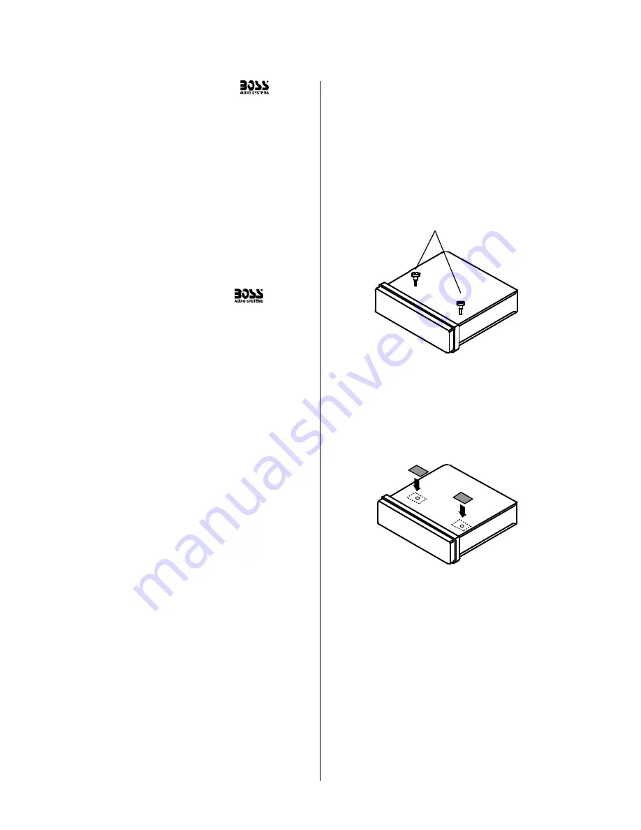
1. Remove the transport screws from
the top of the enclosure before
beginning the installation.
Fig 1
Remove transport screws
2. Place the two pieces of plastic film
provided over the two screw holes to
prevent water penetration.
Figure 2
Apply plastic film to seal screw holes
Figure 3
Bending the support tabs
Figure 9
Insert one end of the panel into the opening
in the main unit. Then push the other end of the
panel into main unit until you hear a “click”
1. Insert one side of the panel fully
into the opening in the main unit.
2. Then push the other end of the
front panel into the main body. You
should hear a “click.”
(Figure 9)
NOTE: If the panel fails to lock into
position properly, the function of
some controls may be impaired,
and some segments of the display
may not become illuminated. If this
occurs, press RELEASE and reinstall
the front panel.
1. Press the RELEASE button to lower
the front panel.
(Figure 5)
.
2. Press the panel release latch on
the front edge of the lower surface of
faceplate, and at the same time pull
the panel forward to disengage it from
the main unit.
(Figure 6)
.
Figure 5
Press RELEASE to release the front panel
RELEASE button
Figure 8
Place the front panel in its protective case
PUSH HERE in this direction
Figure 10
Slots for removal keys
Removal key slots
Before installing your new
CD Receiver, please unpack the contents and check
that your package contains the following items:
RDS EON function setting
The RDS EON system extends the
functionality of the TA sensing to a wider
range of traffic announcements from both
local and national sources. It also allows the
unit to interrupt disc playback with these
announcements. In addition, it will play these
announcements (at normal listening level)
even if the audio has been muted.
(To set this level, see instructions on page
11 for setting V-PGM level).
To enable the EON function, press and hold
the SCAN button. Press again to disable it.
With EON enabled, when a traffic
announcement is broadcast, the radio will
switch automatically to TA mode, and “TP”
(Traffic Program) will be displayed.
PROGRAMMED PLA
Y MODE
In this mode, you can select up to 32 tracks
on a disc to play in an or
der you arrange.
The MEMOR
Y and PROGRAM buttons ar
e
used together for both pr
ogramming and
playback of this mode.
T
o set up a pr
ogrammed playback, following
these steps:
1. Pr
ess and hold MEM to enter the mode.
The P-01 icon will flash on the scr
een,
indicating that it is r
eady to accept the first
playback item.
2. Use the < or > button to move to the
desir
ed track number
. Pr
ess MEM to enter
it. P-02 will flash on the scr
een, indicating
readiness to accept the second item. Use
the < or > button to move to the next track
you wish to pr
ogram, and pr
ess MEM to
enter it.
3. Continue until you have enter
ed all the
desir
ed tracks in this manner
. Pr
ess and hold
the PROG button to complete the
pr
ogramming and begin playback.
4. Pr
ess and hold the PROG button to exit
pr
ogrammed playback mode. T
o start it
again, pr
ess and hold the MEM button, and
then pr
ess and hold the PROG button.
5. T
o clear the memorized playlist, during
pr
ogrammed playback pr
ess and hold the
MEM button. The “CLR” icon will appear on
the display
. Y
ou can confirm this by pr
essing
the PROG button, and seeing the “NO-P”
icon on the display
.
Playing a disc
The disc will begin playing automatically
. If
you wish to pause playback, pr
ess
PLA
Y/P
AUSE, and pr
ess again to r
esume
playback.
Intro Scan function
The Intr
o Scan function is a convenient way
to find a particular track. Pr
ess this button
and the player will play the first few seconds
of a song, and then skip to the next song
and play a few seconds of that song. This
pr
ocess continues until you pr
ess the INTRO
button again, and the player will continue
playing that song.
Repeating a track
T
o keep r
epeating the same track, pr
ess
the REPEA
T button. T
o cancel the r
epeat
function, pr
ess again.
Random play
Pr
essing the RANDOM button will cause
the player to play all the songs on the curr
ent
disc in random or
der
. Pr
ess again to cancel
this function.
2
Head unit installation
4
Detaching the front panel
5
Removing the head unit
6
Remote control installation
Flush mount
6
Remote control installation
Surface mount
10
General and tuner controls
14
Remote control
15
CD Playback
16
RDS radio functions
17
PTY station categories
18
Wiring diagram
19
Troubleshooting
20
Specifications
Congratulations on your
purchase of a
Marine
CD Receiver.
It has been designed, engineered
and manufactured to bring you
the highest level of performance
and quality, and will afford you
years of listening pleasure.
Thank you for making
Marine
your choice for
marine audio entertainment!
page
RDS Model with
Switchable USA/European
Frequencies
SYMPTOM
CAUSE
REMEDY
This list shows the PTY program types in the
order presented in the radio display:
NEWS
AFFAIRS
INFORMATION
SPORTS
EDUCATION
DRAMA
CULTURE
SCIENCE
VARIETY
POP MUSIC
ROCK MUSIC
EASY LISTENING MUSIC
LIGHT MUSIC
CLASSICAL MUSIC
OTHER MUSIC
WEATHER
FINANCE
CHILDREN
SOCIAL
RELIGIOUS
PHONE IN
TRAVEL
LEISURE
JAZZ MUSIC
COUNTRY MUSIC
NATIONAL MUSIC
OLDIES MUSIC
FOLK MUSIC
DOCUMENTARY
ALERT TEST
ALARM TEST
3. Insert and tighten the “headless”
support screw into the back of the
head unit where shown.
4. Insert the mounting case for the
head unit into the dashboard. Inspect
the dashboard material to determine
its approximate thickness. Select the
appropriate support tabs and bend
them outward to secure the bracket
in place
(Figure 3)
.
5. Bend the backstrap to conform to
the mounting case and the dashboard
surface to which you plan to secure
the backstrap
(Figure 4)
. Slide one of
the utility holes on the backstrap onto
the support screw and fasten it with
the spring washer and nut provided.
6. Using the 5 x 25mm screw and the
plain washer, secure the backstrap to
the dashboard surface as shown in
the diagram. Tighten, secure, and
check the overall mounting to be sure
it is safe and will not release in an
emergency stop or other sudden
movement of the vehicle.
Mounting
surface
Drill a 9/16”
(15mm) or
larger hole to
allow cable to
pass through
mounting
surface.
Intallation with cable going
into hole in mounting surface.
Intallation with cable running out on top
of mounting surface.
Figure 6
Press release latch on on the lower surface
of the front edge of the panel and pull the panel until it
is free of the head unit.
Figure 7
Push the panel mechanism back in
Slide the screws out to
extend the mounting arms
so that they reach behind
the mounting surface.
Insert the mounting screws through
the cup into the threaded holes
in the mounting arms
Hold the remote in front of
the cup, turned about
20º counterclockwise.
- OR -
MEM
PROG
MEM
PROG
Содержание MR1600W
Страница 1: ......


