


T
r
oubleshooting
ONYX MOSFET Amplifier User’s Manual - page 18
ONYX MOSFET Amplifier User’s Manual - page 19
ONYX MOSFET Amplifier User’s Manual - page 5
ONYX MOSFET Amplifier User’s Manual - page 9
ONYX MOSFET Amplifier User’s Manual - page 15
ONYX MOSFET Amplifier User’s Manual - page 17
CONTENTS
ONYX MOSFET Amplifier User’s Manual - page 1
U S E R ’ S M A N U A L
General precautions
ONYX MOSFET Amplifier User’s Manual - page 3
Features
About 2 Ohm operation
ONYX MOSFET Amplifier User’s Manual - page 6
ONYX MOSFET Amplifier User’s Manual - page 13
ONYX MOSFET Amplifier User’s Manual - page 14
ONYX MOSFET Amplifier User’s Manual - page 16
ONYX MOSFET Amplifier User’s Manual - page 12
ONYX MOSFET Amplifier User’s Manual - page 8
ONYX MOSFET Amplifier User’s Manual - page 11
ONYX MOSFET Amplifier User’s Manual - page 10
ONYX MOSFET Amplifier User’s Manual - page 7
Specifications
Notes
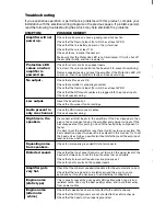
If you experience operation or performance pr
oblems with this pr
oduct, compar
e your
installation with the electrical wiring diagram on the pr
evious pages. If pr
oblems persist,
read the following tr
oubleshooting tips which may help eliminate the pr
oblems.
Pr
otection LED
comes on when
amplifier is
power
ed up.
Check for short circuits on speaker leads.
T
ur
n down the volume control on the head unit to pr
event overdriving.
Remove speaker leads, and r
eset the amplifier
. If the Protection LED
still
comes on, then the amplifier is faulty and needs ser
vicing.
High hiss in the
speakers.
Disconnect all RCA inputs to the amplifiers. If the hiss disappears, then
plug in the component driving the amplifier and unplug its inputs. If the
hiss disappears at this point, go on until the faulty/noisy component is
found.
It is best to set the amplifier's input level control as low as possible. The
best subjective signal-to-noise ratio is achieved in this manner
. T
ry to set
the head unit as high as possible (without distortion) and the amp input
level as low as possible.
Squealing noise
fr
om speakers.
Check for improperly grounded RCA interconnects.
Distorted sound.
Check that the Input Level Control is set to match the signal level of the
head unit. Always tr
y to set the Input Level as low as possible.
Check that all crossover fr
equencies ar
e properly set.
Check for short circuits on the speaker leads.
Amplifier gets
very hot.
Check that the minimum speaker impedance for the amp model is corr
ect.
Check that ther
e is good air circulation around the amp. In some
applications, it may be necessar
y to add exter
nal cooling fan(s).
Engine noise
(static type)
This is usually caused by poor quality RCA cables,which can pick up
radiated noise. Use only the best quality cables, and route them away
from power cables.
Engine noise
(alternator
whine)
Check that speaker leads ar
e not shorted to the vehicle chassis.
Check that the RCA grounds ar
e not shorted to the vehicle chassis.
Check that the head unit is properly grounded.
T
ri-Mode
SHOCK HAZARD! Do not open the case
of this product.
There are dangerous
voltages present within the unit. There are
no user-serviceable parts within the unit.
Before making or breaking power
connections in your system,
disconnect the vehicle battery. Confirm
that your head unit or other equipment
is turned off while connecting the input
jacks and speaker terminals.
If you need to replace the power fuse,
replace it only with a fuse identical to
that supplied with the amplifier. Using
a fuse of a different type or rating may
result in damage to your audio system
or your amplifier which is not covered
by the manufacturer's warranty.
Before installing and using your
new
amplifier, please be-
come familiar with all the infor-
mation contained in this manual.
Please keep this manual in a safe
place for future reference.
• Do not open or attempt to repair
this unit yourself. Dangerous high
voltages are present which may result
in electric shock. Refer any repairs to
a qualified service technician.
• To avoid risk of electronic shock or
damage to the amplifier, do not permit
any of this equipment to become
damp or wet from water or drinks. If
this does occur, immediately unplug
the power wires and send the amplifier
to your local dealer or service center
as soon as possible.
• If there is smoke or any peculiar
odor present during use or if there is
damage to any of the component
enclosures, immediately unplug the
power wire and send the amplifier to
your local dealer or service center as
soon as possible .
Installation precautions
Before you drill or cut any holes,
investigate your car's layout very
carefully. Take special care when you
work near the gas tank, fuel lines,
hydraulic lines and electrical wiring.
Never operate the amplifier when it is
unmounted. Attach all audio system
components securely to prevent
damage, especially in an accident.
Mounting the amplifier
1. Find a suitable location in the vehicle
in which to mount the amplifier.
2. Make sure there is sufficient air
circulation around the intended
mounting location.
3. Mark the location for the mounting
hole screws by positioning the amplifier
where you wish to install it. Use a
scribe or mounting screw, inserted
through each of the amp's mounting
holes, to mark the mounting surface.
If the mounting surface is carpeted,
measure the hole centers and mark
with a felt tip pen.
4. Drill pilot holes in the mounting
surface for the mounting screws. Place
the amplifier in position, and attach
the amplifier to the mounting surface
securely using screws.
7. Insert fuse(s) into the battery fuse
holder(s).
8. Recheck all connections before
powering up the amplifier.
9. Set all level controls to minimum
position, and set all crossover
controls/switches to the desired
frequency points.
10. Power up the head unit and the
amplifier. Then set the volume control
on the head unit to about 3/4 volume,
and adjust the amplifier’s input level
control(s) to just below the level of
distortion.
11. Further fine tuning of the various
controls may be necessary to obtain best
results.
Your ONYX amplifier has been
designed to operate efficiently at loads
down to 2 Ohms. This means that you
can install four 8 Ohm speakers per
channel,
when using parallel wiring.
Increasing the number of woofers per
channel at low frequencies (below
100Hz) produces an acoustic coupling
effect. This acoustic coupling effect
increases your power output by about
3dB per speaker, or the equivalent of
an additional 10W per speaker.
When operating at 2 Ohms, the
amplifiers will increase their output
power by approximately 50%.
The
current draw will also increase by
about the same amount, so be sure
you have enough current to run the
amplifiers into a 2 Ohm load.
If you lack adequate current, your
music reproduction will be distorted.
Low-level (RCA) input wiring is preferred for best audio performance. Always use
a high-quality RCA cable for best audio performance.
Tri-Mode
To Audio
Outputs of head
unit or signal
processor
High Level Input Wiring
Low Level Input Wiring
To Audio Outputs
of head unit or
signal processor
2
Introduction
2
What is included?
3
Features
3
About 2 Ohm operation
4
General precautions
4
Installation precautions
4
Mounting the amplifier
5
Connecting the amplifier
6
Low level input wiring
9
High level input wiring
11
MonoBlock Power and
Speaker wiring
12
2CH Power and Speaker wiring
2CH Mode
13
2CH Power and Speaker wiring
Bridged Mode
14
2CH Power and Speaker wiring
TriMode
15
4CH Power and Speaker wiring
4CH Mode
16
4CH Power and Speaker wiring
Bridged Mode
17
4CH Power and Speaker wiring
TriMode
18
Troubleshooting
19
Specifications
page
All specifications subject to change without notice.
RMS POWER
into 4 Ohms
MAX POWER
into 2 Ohms
BRIDGED POWER
into 4 Ohms
Min. speaker
impedance
THD
Fr
equency r
esponse
Signal-to-noise ratio
Channel separation
Damping factor
Cr
ossover range
low pass
high pass
Bass boost
Fuse rating
Dimensions:
(10" x 2
-3/16
" x ...)
MODEL
4-Channel MOSFET Amplifiers
RMS POWER
into 4 Ohms
MAX POWER
into 2 Ohms
BRIDGED POWER
into 4 Ohms
Min. speaker
impedance
THD
Fr
equency r
esponse
Signal-to-noise ratio
Channel separation
Damping factor
Cr
ossover range
low pass
high pass
Bass boost
Fuse rating
Dimensions:
(10" x 2
-3/16
" x ...)
MODEL
2-Channel MOSFET Amplifiers
1500W x 1
2800W X 1
n/a
2 Ohm Ster
eo
4 Ohm Mono Bridged
0.01%
15-250Hz
100dB
90dB
125+
35Hz-160Hz
n/a
V
ariable 0 - +18dB
25A x 2
15-1/8"
SYMPTOM
POSSIBLE REMEDY
Connect the Positive (+) terminal of the
subwoofer to the L (+) amplifier terminal.
Connect the Negative (-) terminal of the
subwoofer to the R (-) amplifier terminal.
Two
Channel
Mode
Bridged
Mode
Four Channel Mode
Bridged Mode
Connect the Postive (+) terminal of the RIGHT
subwoofer to the CH3(+) amplifier terminal.
Connect the Negative (-) terminal of the RIGHT
subwoofer to the CH4(-) amplifier terminal.
Connect the Postive (+) terminal of the LEFT
subwoofer to the CH1(+) amplifier terminal.
Connect the Negative (-) terminal of the LEFT
subwoofer to the CH2(-) amplifier terminal.
Chassis
ground
point
To FRONT
Audio Outputs
of head unit or
signal processor
To REAR
Audio Outputs
of head unit or
signal processor
To Speaker Terminals
of head unit
To Speaker Terminals
of head unit


