


24
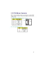
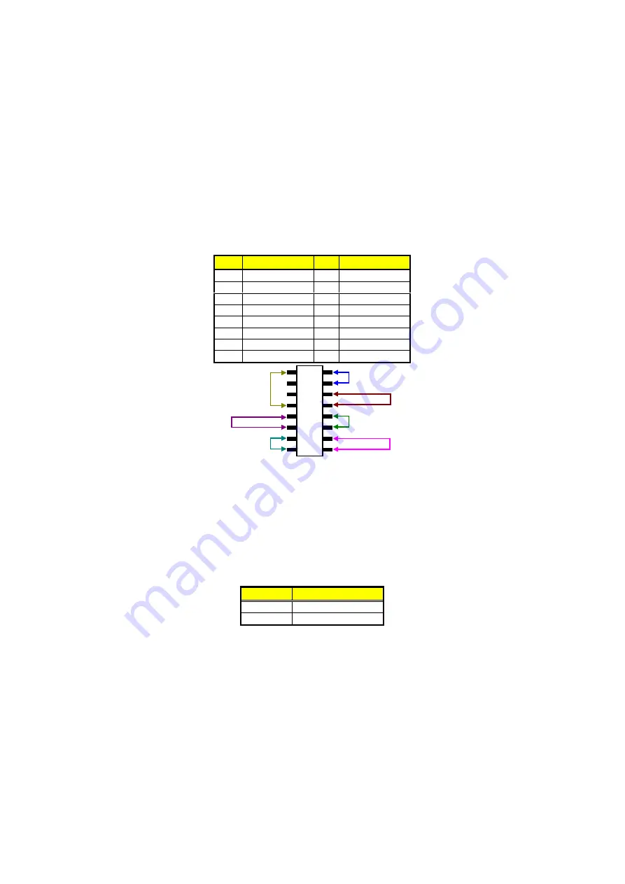
3.20 System Front Panel Connectors
The HS-6252 has one LED at location
JP1(2-4)
that indicates the
power-on status. This visual feature of the IDE LED may also be
connected to an external IDE LED via connector
JP1(13-15)
.
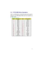
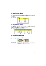
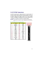
JP1: System Front Panel Connector
PIN Description PIN Description
1
VCC
2
330
Ω
Pull +5V
3
GND
4
GND
5
N/C
6
EXT SMI
7
Speaker
8
GND
9
GND
10
Power Button
11
Reset Switch
12
GND
13
330
Ω
Pull +5V
14
Sleep Button
15
HDD LED
16
GND
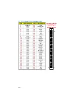
1
3
5
7
9
11
13
15
2
4
6
8
10
12
14
16
PWR LED
PWR button
SLP button
EXT_SMI
HD_LED
RST_SW
SPEAKER
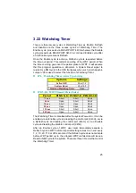
3.21 Thermal Input Connector
In relevance to the Hardware Monitoring feature provided by the
onboard VIA VT82C686B, the board allows the installation of a thermal
sensor via connector
RT1
. The thermal connector monitors and
displays the current system temperature from the Chipset Features
Setup screen on your BIOS utility program. The value displayed is
read-only figures and may not be altered.
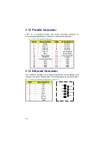
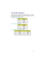
RT1: Thermal Input Connector
PIN
Description
1
Sensor In
2
GND
Содержание HS-6252
Страница 6: ...This page intentionally left blank...
Страница 10: ...4 1 3 Board Dimensions...
Страница 14: ...8 3 2 Board Layout...
Страница 36: ...30 This page intentionally left blank...
Страница 60: ...54 This page intentionally left blank...
Страница 90: ...84 This page intentionally left blank...


