Boser BPC-5015 Скачать руководство пользователя страница 13


7

Chapter 3 

Hardware Installation 

This chapter illustrates how to install components into the Panel PC 
system. External interface please refers to system board’s manual. 

3.1  HDD/CD-ROM/PCI Card Installation 

1. Remove the HDD drive bay holding bracket. 


2. Install the holding bracket with HDD. 


Содержание BPC-5015

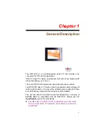
Страница 1: ...BPC 5015 15 High Speed Panel PC with one PCI slot 180W ATX P S...

Страница 2: ...granted permission by BOSER Technology Co Ltd BOSER Technology Co Ltd reserves the right to change or improve the contents of this document without due notice BOSER Technology Co Ltd assumes no respon...

Страница 3: ...ifications 3 1 4 Control Keys 3 1 5 Dimensions 4 Chapter 2 Unpacking 5 2 1 Opening the Delivery Package 5 2 2 Inspection 5 Chapter 3 Hardware Installation 7 3 1 HDD CD ROM PCI Card Installation 7 Chap...

Страница 4: ...mpleted on a sample of the equipment identified below Equipment Class Information Technology Equipment Product Model Series BPC 5015 This Product Complies With EN55022 Class A for Radiated emissions E...

Страница 5: ...r cord is damaged in anyway Do not insert objects into openings Do not immerse product in water or permit liquids to spill inside Turn off power when unattended or not in use Unplug product before mov...

Страница 6: ...y brightness decreases over time with use The expected operating lifetime of the backlight time to reach 50 initial brightness is 30 000 hours assuming continuous lit state at 25 degrees C Actual life...

Страница 7: ...n needed The BPC 5015 has a 15 touch screen that operates under all types of working environment It comes with a reliable power supply and three 4cm ball bearing cooling fan that enhance system stabil...

Страница 8: ...t in OSD key touch screen HS 1750 WLAN module 180W ATX P S Provides Intel Core Duo T2050 processor Onboard graphics dual GB ethernet audio controller Standard 5V PCI expansion slot x 1 COM x 4 USB2 0...

Страница 9: ...all bearing cooling fan x 3 Power In 180W ATX power supply Temperature 0 45 C operating 20 70 C storage Dimensions 42 0 L x 33 0 H x 8 79 W cm 1 3 Panel Specifications Screen Size 15 inches Display Fo...

Страница 10: ...4 1 5 Dimensions...

Страница 11: ...mely careful to prevent any damages to the board from static Integrated circuits will sometimes come out from sockets during shipment Examine all integrated circuits particularly the BIOS processor me...

Страница 12: ...6 This page intentionally left blank...

Страница 13: ...ter illustrates how to install components into the Panel PC system External interface please refers to system board s manual 3 1 HDD CD ROM PCI Card Installation 1 Remove the HDD drive bay holding bra...

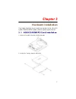
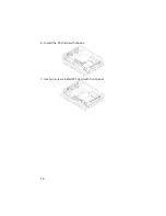
Страница 14: ...8 3 Remove the CD ROM drive holding bracket 4 Install the holding bracket with CD ROM...

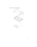
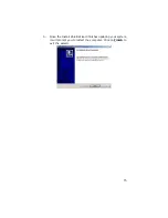
Страница 15: ...9 5 Install the PCI Card holding bracket...

Страница 16: ...10 6 Install the PCI Card with chassis 7 Use two screws install PCI Card with front panel...

Страница 17: ...h screen driver The following sections describe the installation procedures of driver based on WIN2000 operating systems Other operation system may slightly different 4 1 Touch Screen Driver Installat...

Страница 18: ...12 3 The next screen is Software License Agreement select I accept and click on Next 4 The next screen is Ready to Install the Program click on Install...

Страница 19: ...r Click on Finish to exit the wizard 4 1 2 Installing Touch Screen Driver in WIN2000 1 Insert Utility CD Disk to your CD ROM drive The main menu will pop up as shown below 2 The screen displays copyin...

Страница 20: ...14 3 The next screen is Software License Agreement select I accept and click on Next 4 The next screen is Ready to Install the Program click on Install...

Страница 21: ...15 5 Once the Install Shield Wizard finishes updating your system it will prompt you to restart the computer Click on Finish to exit the wizard...

Страница 22: ...display with touch screen click on Calibrate button and follow the calibrate point to do the calibration there are five points on screen for calibration Draw Test or demonstrate PenMount touch screen...

Страница 23: ...Control Panel When select this function there is a mouse icon shown in the right button place of screen It shows Left Button being as default for normal use change Right Left button by clicking the m...

Страница 24: ...18 This page intentionally left blank...

Отзывы: