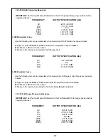
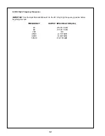
Bose 1800-V Скачать руководство пользователя страница 35

35

Item

Number

Decription

Part Number

Qty
Per

Assy

See

Note

20

Screw,SEMS PP BLKOX WX 6-
32x3/8

182724

6

21

Clamp, Cable, Nylon 1.38"

182732

1

22

Bracket, Heatsink

182741

2

23

Fan, 24 VDC High Flow, B1

182710

1

24

Post, BDG, Dual Short Red/BLK
120V & 100V

182711

2

Post, BDG, Dual Short RT Entry
230V

182712

1

Post, BDG, Dual Short LT Entry
230V

182713

1

25

Plug, Terminal Blanking, Red 230V

182714

2

Plug, Terminal Blanking, Blk 230V

182715

2

26

Shield, Fan, Lower

182751

1

27

Shield, Fan, Upper

182748

1

28

Screw, BLK, FH 100DEG  
6-32x1-1/4

182718

4

29

Screw, Pan HD #4 SLFTPG
W/WSHR 1/2"

182722

32

30

Screw SHT MTL PP BLK 4x9/16

182720

6

31

Line Cord Europe, 16A, 7' 230V

182737

1

1

Line Cord, 14/3 SJT SHLD 15A
Dom. 7, P1 120V & 100V

182738

1

1

32

Fuse Holder Panel MNT 120-230V

182706

1

33

Fuse Carrier 120V & 100V

182707

1

Fuse Carrier 230V Europe

182708

1

34

Fuse,15 Amp,250V, F1, for100V &
120V

182736

1

1

Fuse, 8 Amp, Time Lag, for 240V

183551

1

1

35

Insulation,Film

182709

36

Strain Relief, Threaded

182716

1

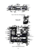
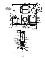
1800-V MAIN ASSEMBLY PART LIST

!

!

NOTE:

1.         This part is critical for safety purposes. Failure to use a substitute replacement with the
same safety characteristics as the recommended replacement part might create shock, fire and/or
other hazards.

!

Содержание 1800-V

Страница 1: ...Figure 19 Top Down Inside Views 38 1800 V PACKAGING PART LIST 39 Figure 20 1800 V Amplifier and EQ Card Packaging Illustration 39 1800 V ELECTRICAL AND MECHANICAL PART LISTS 40 Display PCB Electrical...

Страница 2: ...ed metal parts that offer an electrical return path to the chassis Any current measured must not exceed 0 5 milliamp Reverse the unit power cord plug in the outlet and repeat test ANY MEASUREMENTS NOT...

Страница 3: ...ation Wear wrist straps that connect to the station or heel straps that connect to conduc tive floor mats Avoid touching the leads or contacts of ESDS devices or PC boards even if prop erly grounded H...

Страница 4: ...0 kHz with no more than 0 2 THD Voltage Output 61 6V line voltage per channel into 8 ohms Dynamic Headroom 1 0 dB nominal Power Bandwidth 5 Hz to 40 kHz 0 3 dB Frequency Response 20 Hz to 20 kHz 0 75...

Страница 5: ...10V S Bandwidth limited 40V S RFI filtering removed CMRR 80 dB 1 kHz without Bose Input Module 60 dB from 20 Hz 20kHz without Bose Input Module Power Consumption 40W at idle 800W with musical program...

Страница 6: ...Figure 2 402 EQ Card Full Range Response Figure 1 402 EQ Card HF Only Response FREQUENCY CURVES 6...

Страница 7: ...Figure 3 502A EQ Card HF Only Response Figure 4 502A EQ Card Full Frequency Response 7...

Страница 8: ...Figure 6 802 EQ Card HF Only Response Figure 5 502B EQ Card Response 8...

Страница 9: ...Figure 7 802 EQ Card Full Range Response 9...

Страница 10: ...utation Control Class H Power Supplies On Off Standby Power Fuse 230V Only Regulation Phase Control Lowpass Filter Temperature Sense Protection Display Drive Display Level Control Sequence Control Inp...

Страница 11: ...Input Module motherboard Additional Features are as follows Two input connectors per channel allow 1 4 TRS XLR or quick connect terminal block connection Two input connectors for each channel are wire...

Страница 12: ...o ICs U1 and the CH2 signal to U2 U1 and U2 are unity gain 0 dB differential amplifiers SSM2141 These inputs are protected against RFI Radio Frequency Interference and ESD Electro Static Discharge The...

Страница 13: ...inputs for input and feedback connections as well as most of the open loop voltage gain of the circuit Local and global negative feedback from the output stage via R109 R113 R111 R112 and R129 sets th...

Страница 14: ...by R10 at pin 3 Where pin 2 crosses the threshold the output of U4C 1 goes open and C6 begins to charge through R21 and U4A 8 U4A is a voltage to current converter Howland current pump whose output cu...

Страница 15: ...amplifier U5A 1 senses this and increases the LED current to optocoupler U1 This action increases the phototransistor conduction which increases the output current of U4 8 increasing the charging rat...

Страница 16: ...ithout this approach the output transistors would be required to support the entire power supply voltage under small signal conditions and the unused portion of the power supply voltage would be turne...

Страница 17: ...tors to each other When U1A 1 fires the current through R24 reverses the sequence of the voltages that establish the thresholds for the three comparators This allows the same comparators to perform do...

Страница 18: ...to become less positive shutting off the conduction current through optocoupler U1 which shuts off the triac and primary current 3 4 Overheated Output Transistors A thermistor RT100 is positioned near...

Страница 19: ...cted in parallel with the CH 2 input but in phase The CH 1 input connection becomes disabled This allows both channels to be driven with the same signal without the use of special patch cords Each cha...

Страница 20: ...inals 6 11 4 4 Return the cover 1 to the chassis 2 see Procedure 2 5 Regulator Board Removal NOTE Refer to Figures 11 and 12 for this procedure 5 1 Remove the cover 1 see Procedure 1 5 2 To have bette...

Страница 21: ...16 wrench The screws are driven from the bottom of the chassis Refer to Figures 13 and 14 5 3 Unsnap the Regulator Board from the nylon standoffs mounted on the Power Supply Board This will also dise...

Страница 22: ...eatsink Item 18 Figure 10 Rear View Attaching Hardware Qty 2 3 3 3 Qty 2 11 11 AC 1800 W 50 60Hz 100V CONSULT OWNERS MANUAL 1800 SERIES V PROFESSIONAL AMPLIFIER LICENSED UNDER U S PAT NO 4 484 150 D O...

Страница 23: ...connectivity 12 4 Return the cover 1 to the chassis 2 see Procedure 2 13 Amplifier Board Removal 13 1 Remove the cover 1 see Procedure 1 13 2 Disconnect the following cables Refer to Figure 12 The two...

Страница 24: ...back panel Refer to Figure 14 15 5 To release the heatsink base from the bottom of the chassis use a phillips head screwdriver to remove four screws 3 from the chassis s bottom panel Refer to Figure 1...

Страница 25: ...ttaches Bracket to Heatsink Heatsink Bracket 2 Chassis I O Board Part of 9 2 16 43 17 23 4 T1 J1 28 24 B1 Qty 2 11 Qty 4 26 27 12 33 34 32 6 7 8 9 10 11 2 1 5 3 4 10 Qty 2 11 12 FL1 E1 12 14 Qty 4 F1...

Страница 26: ...nect the I O Board s 6 ribbon cable to the Output Board s J2 connector Refer to Figure 13 16 6 Connect the fan s 23 connector to the Output Board s J3 connector Refer to Figure 13 16 7 Place the heats...

Страница 27: ...is s back panel by removing two screws 3 with a phillips head screwdriver The screws are located over the fan s exhaust slot Refer to Figure 10 19 4 Release the lower shield from the bottom of the cha...

Страница 28: ...crews 11 with the phillips head screwdriver The screws are driven from the outside of the back panel Refer to Figure 10 22 5 Use Procedure 16 Steps 16 7 16 11 to install the heatsink 18 and cabling 22...

Страница 29: ...While following the test conditions outlined above the total harmonic distortion should be 5 1 kHz for all amplifier outputs 1 2 Low Level Distortion Set the CH1 and CH2 Level Controls to obtain 6 25...

Страница 30: ...FREQUENCY OUTPUT SPECIFICATION dbr 60 3 7 1 5 dB 105 8 5 1 5 dB 220 3 5 1 5 dB 850 0 0 4000 5 8 1 5 dB 14500 13 3 1 5 dB FREQUENCY OUTPUT SPECIFICATION dbr 60 16 4 1 5 dB 105 4 8 1 5 dB 220 2 8 1 5 dB...

Страница 31: ...output C Measure the response according to the charts in Sections 4 1 and 4 2 2 2 502A High Frequency Response IMPORTANT Set the Input Module s S2 switch to the HF Only High Frequency position before...

Страница 32: ...se IMPORTANT Set the Input Module s S2 switch to the HF Only High Frequency position before beginning this test FREQUENCY OUTPUT SPECIFICATION dbr 40 21 0 1 5 dB 60 11 5 1 5 dB 700 0 0 2500 2 1 1 5dB...

Страница 33: ...h PCB Assembly Amplifier PCB Assembly Output PCB Assembly Input Module Assembly includes Input PCB Barrier PCB and Dual Input Panel Assembly 402 Equalizer PCB Assembly 502A Equalizer PCB Assembly 502B...

Страница 34: ...230V 182764 1 1 11 Screw SEMS PP BLKOX WX 6 32x1 4 182723 10 12 Nut Lock 6 32 X 5 16 Zinc 182728 9 13 Screw Mach PP BLK 10 32x3 8 182719 4 14 Washer Int Lock 10 CAD PLTD 182730 8 15 CCA Amplifier 182...

Страница 35: ...6 32x1 1 4 182718 4 29 Screw Pan HD 4 SLFTPG W WSHR 1 2 182722 32 30 Screw SHT MTL PP BLK 4x9 16 182720 6 31 Line Cord Europe 16A 7 230V 182737 1 1 Line Cord 14 3 SJT SHLD 15A Dom 7 P1 120V 100V 1827...

Страница 36: ...182747 4 49 Shield Pot Noise 182750 1 50 Narness Conn 13 Pin 22 Awg 23 182754 1 51 Bracket Connector 182742 1 52 Bracket Shield 182743 1 53 Switch Rocker SPST QICDIS 15A for 240V 183550 1 1 54 402 Equ...

Страница 37: ...60Hz 100V CONSULT OWNERS MANUAL 1800 SERIES V PROFESSIONAL AMPLIFIER LICENSED UNDER U S PAT NO 4 484 150 D O M BOSE CORPORATION FRAMINGHAM MA 01701 9168 MADE IN U S A AVIS CAUTION WARNING DO NOT EXPOS...

Страница 38: ...5 3 4 J1 21 15 100V and 120V Configuration J1 I O Board Part of 9 2 16 43 17 23 4 T1 J1 A3 28 24 B1 Qty 2 11 Qty 4 26 27 12 33 34 32 6 7 8 9 10 11 2 1 5 3 4 10 Qty 2 11 12 FL1 E1 12 14 Qty 4 F1 Qty 2...

Страница 39: ...hipping Amplifier 177326 1 2 Packing Insert Amplifier 182752 1 3 Packaging Foam 182753 4 4 Manual User 179353 1 1 5 Polybag Amplifier 182768 1 6 Literature Kit EQ Cards 178857 1 7 Bag Antistatic EQ Ca...

Страница 40: ...K 1 1 4W MF 182977 R16 21 23 27 29 32 7 5K 1 1 4W MF 182978 R103 149 164 203 10K 5 1 4W CF 182789 R104 204 3 3K 5 1 4W FLMPRF 182979 R112 212 7 5K 5 1 2W CF 182975 R113 142 202 213 2 2K 5 1 4W CF 1827...

Страница 41: ...Q100 200 TO92 PNP SM SG 2N4125 182815 Reference Designator Description Part Number Reference U1 4 Dual Op Amp 4558 8 PIN SIP 182914 Reference Designator Description Part Number Reference J1 Header 13...

Страница 42: ...CF 182902 R19 70 30K 5 1 4W CF 182852 R21 22 71 72 27K 5 1 4W CF 182903 R23 73 510K 5 1 4W CF 182798 R24 74 330K 5 1 4W CF 182904 R29 77 910 5 1 4W FLMPRF 182810 R31 79 4 7K 5 1 4W CF 182796 R40 83 2...

Страница 43: ...96 C16 32 10 F 20 50V LYTIC RAD 182895 Reference Designator Description Part Number Reference D1 2 6 9 12 18 20 24 27 29 30 34 36 1N4148 75V 182868 D3 4 Bridge Rectifier 50V 1 0 AMP DF005 182912 D5 19...

Страница 44: ...PIN SIP 182914 U3 8 Optoisolator VTL5C4 199766 Reference Designator Description Part Number Reference J1 Harn Conn 20 Pin 28 Awg 6 182919 J100 200 Header 10 Pin Rt Angle Square 182888 J3 Header 13 Pi...

Страница 45: ...43 61 511 1 4W 1 MF 182858 R14 28 45 58 681 1 1 4W MF 182859 R16 47 3K 5 1 4W CF 182851 R17 23 39 48 54 71 10K 5 1 4W CF 182789 R18 49 5 1K 5 1 4W CF 182855 R19 50 30K 1 4W 5 CF 182852 R20 35 51 66 91...

Страница 46: ...835 C14 22 30 36 100 F 20 25V LYTIC AX 95 D 182843 C15 23 31 37 01 F 20 500V Cer Disc 182836 C16 17 24 25 047 F 200V Cer Multilayer RD A 182837 C38 41 01 F 100V CER Multilayer RD A 182780 C44 45 10 F...

Страница 47: ...82871 Q9 14 20 25 FET POWER IRFZ44 182878 Q10 21 TO92 PNP SM SG MPSA93 182873 Reference Designator Description Part Number Reference U1 Opto Triac Driver MOC3052 182880 U2 3 Dual Volt Comparators LM39...

Страница 48: ...7 4 Standoff Brs 25 Od 6 32 Swg 125 B 182828 2 Heatsink Power Supply 182884 1 Heatsink Bridge 182885 1 Insulator Sil Pad K 6 8 Pos 182886 1 Insulator Sil Pad K6 To 218 182887 1 Screw Mach Pp 6 32x3 4...

Страница 49: ...1 4W MF 182801 R13 3 32K 1 1 4W MF 182958 R14 17 10K 5 1 4W CF 182789 R15 1K 5 1 4W CF 182788 R16 15K 5 1 4W CF 182848 R19 21 10K 1 1 4W MF 182800 R20 30K 5 1 4W CF 182852 R23 24 20K 1 1 4W MF 182957...

Страница 50: ...0V Cer Disc 182944 C6 1 F 5 100V PLYFLM RAD 182945 C7 10 F 20 50V LYTIC RAD 182895 C9 10 01 F 100V Cer MULTILYR RD 182780 Reference Designator Description Part Number Reference D2 3 Zener 1N4736A 6 8V...

Страница 51: ...05P 182964 U5 Dual Op Amp 4558 8 Pin SIP 182914 Reference Designator Description Part Number Reference J1 Header 18 Pin Sgl Row 100 Gld 182943 Power Switch PCB Electrical Part List Reference Designato...

Страница 52: ...1 1 4W MF 182803 R110 210 2 2K 5 1 4W CF 182793 R111 112 211 212 909 MF 1 1 4W 182804 R113 213 100K 1 1 4W MF 182801 R122 222 16K 5 1 4W CF 182791 R123 223 3 6K 5 1 4W CF 182794 R124 224 Potentiometer...

Страница 53: ...IC AX 80 D 182782 C105 107 205 207 50 pF 10 1000V Cer Disc 182777 C106 206 22 pF 10 1000V Cer Disc 182776 C109 209 4 7 F 20 50V LYTIC AX 80 B 182784 C110 111 01 F 100V Multilayer CER RD 182780 C112 11...

Страница 54: ...10 112 114 116 118 120 208 210 212 214 216 218 220 XSTR TO3P L NPN PWR 2SC3281 0 182813 Q109 111 113 115 117 119 121 209 211 213 215 217 219 221 TO3P L PNP PWR 2SA1302 0 B 182814 Q122 222 TO92 PNP SM...

Страница 55: ...470 2W 1 0 AX LG 182933 R103 203 WW LRES 5 02 5W 1 2 AX 182935 R110 210 1 5 5W 1 2 MO AX SM 182931 R111 211 1 5 1 4W FLMPRF 182861 R112 113 212 213 10 5 1 4W FLMPRF 182937 R114 214 1 1K 5 1 4W CF 182...

Страница 56: ...Number J2 Header 14 Pin Dual Row 1 Gld A 182922 J3 Header 2 Pin 1 Lock St Post 182921 Reference Designator Description Part Number Reference K100 200 Relay SPDT 24V 20A 182942 L100 200 Choke 5uH 14 Wi...

Страница 57: ...5 1 4W CF 182994 R86 89 390 5 1 4W CF 182951 Reference Designator Description Part Number Reference C37 40 330pF 5 100V Cer Disc GP 182992 C41 42 3 300pF 10 100V Ceramic Disc 183883 C43 220 F 20 16V...

Страница 58: ...ference J1 Header 20 Pin Dual Rw 1 Post 3 182988 J2 Hdr Rt Angle Blind Mate 4 Pin A 182991 J3 Header 2 Pin 1 Lock St Post 182921 J4 5 Header 90 Deg Clsd End 3 Pin 182990 J6 7 Header 12 Pin 098 Ctr Shr...

Страница 59: ...Reference PC Board Barrier 182968 Description Location Part Number Qty Per Assy Reference Plug RT Angle Terminal Block 3 pin J4 J5 182769 2 Screw Metric MA PP BLK M3X8MM 182770 4 Screw SEMS PP BLKOX...

Страница 60: ...7872 R37 38 47K 5 Chip 124895 4735 Reference Designator Description Part Number Reference C2 1uF 5 BOX FILM 137127 104 C3 27uF 5 BOX FILM 137127 274 C4 0047uF 5 BOX FILM 137127 472 C5 680pF 10 CER 13...

Страница 61: ...Chip 124894 4021 R5 20 Jumper Chip 124896 R8 30 1K 1 Chip 124894 3012 R11 49 9K 1 Chip 124894 4992 R12 2 32K 1 Chip 124894 2321 R14 13K 1 Chip 124894 1302 R15 20 0K 1 Chip 124894 2002 R16 1 33K 1 Chi...

Страница 62: ...5 137127 474 C24 26 48 51 10000pF 80 20 CHIP 124959 103 C25 047uF 5 63V BOX 85 137127 473 Reference Designator Description Part Number Reference D1 3 5 Axial 1N4148 26MM 121501 D4 6 Zener 5 18V 1W 116...

Страница 63: ...4 6981 R47 1 00K 1 Chip 124894 1001 R48 4 32K 1 Chip 124894 4321 R49 5 49K 1 Chip 124894 5491 R50 51 14 0K 1 Chip 124894 1402 Reference Designator Description Part Number Reference C26 27 100pF 50V 10...

Страница 64: ...eference R1 13K 1 Chip 124894 1302 R2 1 00K 1 Chip 124894 1001 R3 4 18K 5 Chip 124895 1835 R5 13 14 19 20 Jumper Chip 124896 R8 20 0K 1 Chip 124894 2002 R9 2 74K 1 Chip 124894 2741 R10 23 7K 1 Chip 12...

Страница 65: ...37127 154 C23 0012uF 5 Box Film 137127 122 C24 26 48 51 10000pF 80 20 CHIP 124959 103 C25 068uF 5 Box Film 137127 683 Reference Designator Description Part Number Reference D1 2 3 5 Axial 1N4148 26MM...

Страница 66: ...12 11 10 9 8 7 6 5 4 3 2 1 1 2 3 4 5 6 7 8 9 10 11 12 13 14 10 9 8 7 6 5 4 3 2 1 1 2 3 4 5 6 7 8 9 10 1 2 3 4 5 6 7 8 9 10 11 12 13 14 15 16 10 9 8 7 6 5 4 3 2 1 1 2 3 4 5 6 7 8 9 10 16 15 14 13 12 11...

Страница 67: ...E1 E2 E3 SWITCH W24 W22 E16 WL6 WL7 W60 W3 E17 W5 W1 W2 SWITCH FUSE 8 AMP F1 RED WHT BLU BLK J1 J1 REGULATOR CCA SUPPLY CCA POWER TIP RING WL4 WL5 BRN BLU W7 W6 SEQUENCE S1 POWER SWITCH W4 E1 GRN YEL...

Страница 68: ...ds are located on Pages 69 74 There are separate schematic and layout foldout sheets for the following PCB assemblies Display PCB Assembly Input Output I O PCB Assembly Power Supply PCB Assembly Regul...

Страница 69: ...402 Equalizer Card Schematic 69...

Страница 70: ...502A Equalizer Card Schematic 70...

Страница 71: ...502B Equalizer Card Schematic 71...

Страница 72: ...802 Equalizer Card Schematic 72...

Страница 73: ...73 402 502A AND 802 Equalizer Card PC Board Layouts PC Board Number 177328 Revision 01 Top Components Top Etch Layer Top Components Bottom Etch Layer SMD Components Bottom Etch Layer...

Страница 74: ...502B Equalizer Card PC Board Layouts PC Board Number 178860 Revision 0 Top Components Bottom Etch Layer SMD Components Bottom Etch Layer Top Components Top Etch Layer...

Страница 75: ...IFICATIONS AND FEATURES SUBJECT TO CHANGE WITHOUT NOTICE Bose Corporation The Mountain Framingham Massachusetts USA 01701 P N 181812 11 95 Rev 0 FOR TECHNICAL ASSISTANCE OR PART ORDERS CALL 1 800 367...

Отзывы: