background image

64

en | Using the AutoDome 800 Series

AutoDome 800 Series HD PTZ Camera

F.01U.273.797 | 5.0 | 2012.08

Installation Manual

Bosch Security Systems, Inc.

1.

If you want to delete the entries, click the delete icon in the top right-hand corner of the 

relevant field.

2.

If you want to view a detailed log, click the icon in the top right-hand corner of the 

relevant field. A new window will open.

6.6.1

Entering a Keyboard Control Command

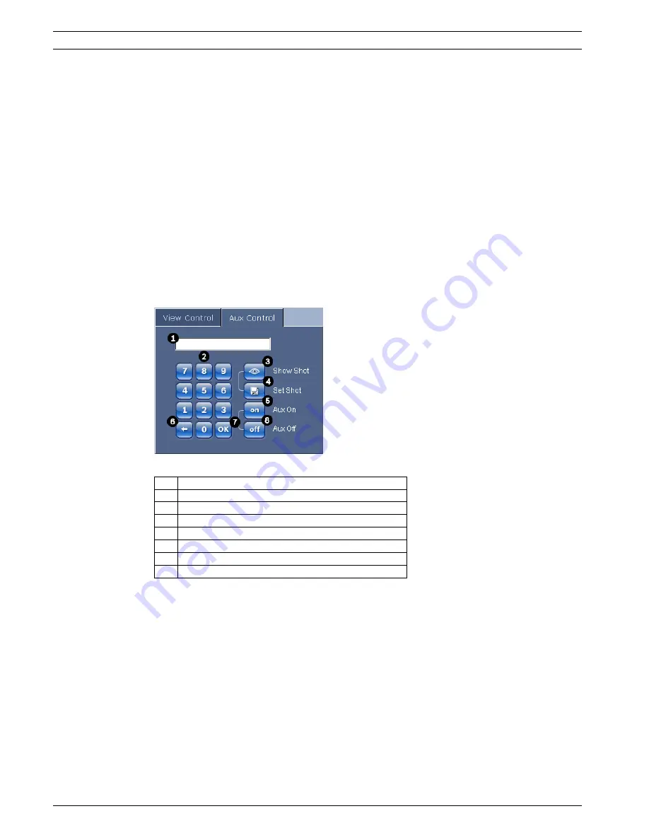
The Aux Control tab is used to enter keyboard control commands. These commands are 

composed of a command number plus the appropriate function key (Show Shot, Set Shot Aux 

On or Aux Off). A valid combination either issues a command to the camera or displays an on-

screen menu.

Aux Control Tab

The Aux Control tab is used to enter pre-programmed keyboard control commands. 

See 

Section A Keyboard Commands by Number, page 116

, for a list of all commands. 

To access the Aux Control tab, navigate to the Livepage and click the Aux Control tab (see 

Figure 6.3

 below). 

Figure 6.3

Aux Control Tab

To Enter a Keyboard Control Command:

1.

Place the cursor in the Command Number field.

2.

Click the desired command number via the on-screen keypad.

3.

Click either the Aux On or the Aux Off button to initiate or stop the command.

4.

If the command initiates a menu, use the Up/Down arrows on the View Control to 

navigate the menu. Click the Focus or Iris button to select a menu item.

To Set a Preset Shot:

Preset shots (or scenes) are camera positions that are saved in memory for future use.

1.

Move your cursor over the live image and wait for the area to display a directional arrow.

2.

Click and hold a mouse button to pan to the desired position you want to save.

3.

Click any number combination from 1-99 from the on-screen keypad to identify the scene 

number.

4.

Click the Set Shot button. The image area displays a message that indicates which shot 

number was saved.

1

Command number field

2

Keypad (numbers 0-9)

3

Show a preset shot

4

Set a preset shot

5

Initiates a command

6

Deletes a number in the Command Number field

7

Used to select a menu item

8

Stops a command

Содержание VG5 800 SERIES

Страница 1: ...AutoDome 800 Series HD PTZ Camera VG5 800 Series en Installation Manual ...

Страница 2: ......

Страница 3: ...8 Installing the VG4 A ARMPLATE 26 2 8 1 Attach the Pendant Arm to the Mounting Plate 27 2 8 2 Route and Connect Wires to a Power Supply Box 27 2 9 Attach Pendant to Arm and Tighten 31 3 Installing Roof Parapet and Pipe Mounts 33 3 1 Unpacking 33 3 1 1 Parts List 33 3 1 2 Description 33 3 1 3 Tools Required 33 3 2 Pre installation Check List 34 3 3 Mount Power Supply Box 34 3 3 1 Attach Cover Door...

Страница 4: ...enting Intelligent Tracking 61 6 6 The Livepage 61 6 6 1 Entering a Keyboard Control Command 64 6 6 2 Using Intelligent Tracking 65 6 6 3 Using Special Functions 65 6 7 Saving Snapshots 66 6 8 Recording Video Sequences 66 6 9 Processor Load 66 6 10 Recordings page 68 6 10 1 Controlling playback 68 7 Configuring the AutoDome 800 Series 70 7 1 Basic Mode Device Access 70 7 2 Basic Mode Date Time 71 ...

Страница 5: ...7 7 41 Audio Alarm 101 7 42 Alarm E Mail 102 7 43 Alarm Task Editor 103 7 44 Alarm Rules 103 7 45 Advanced Mode Interfaces 104 7 46 Alarm Inputs 104 7 47 Relay 104 7 48 Advanced Mode Network 105 7 49 Network Access 105 7 49 1 IPv4 105 7 49 2 IPv6 106 7 49 3 Detailed Settings 106 7 50 Advanced 108 7 51 Multicast 109 7 52 FTP Posting 110 7 53 IPv4 Filter 111 7 54 Encryption 111 7 55 Advanced Mode Se...

Страница 6: ...6 en Table of Contents AutoDome 800 Series HD PTZ Camera F 01U 273 797 5 0 2012 08 Installation Manual Bosch Security Systems Inc A Keyboard Commands by Number 116 Index 117 ...

Страница 7: ...h objects of any kind into this unit through openings as they may touch dangerous voltage points or short out parts that could result in a fire or electrical shock Never spill liquid of any kind on the unit Do not place objects filled with liquids such as vases or cups on the unit 6 Lightning For added protection during a lightning storm or when leaving this unit unattended and unused for long per...

Страница 8: ...equiring service Unplug the unit from the main AC power source and refer servicing to qualified service personnel when any damage to the equipment has occurred such as the power supply cord or plug is damaged exposure to moisture water and or inclement weather rain snow etc liquid has been spilled in or on the equipment an object has fallen into the unit unit has been dropped or the unit cabinet i...

Страница 9: ...omply and be tested in accordance with UL IEC60950 Any output or signal lines from the camera must be SELV or Limited Power Source For safety reasons the environmental specification of the camera lens assembly must be within the environmental specification of 10 C 14 F to 50 C 122 F Camera signal Protect the cable with a primary protector if the camera signal is beyond 140 feet in accordance with ...

Страница 10: ...rcuit protection must be secured with a maximum fuse rating of 16A This must be in accordance with NEC800 CEC Section 60 Grounding and polarization This unit may be equipped with a polarized alternating current line plug a plug with one blade wider than the other blade This safety feature allows the plug to fit into the power outlet in only one way If unable to insert the plug fully into the outle...

Страница 11: ... radiates radio frequency energy and if not installed and used in accordance with the instruction manual may cause harmful interference to radio communications Operation of this equipment in a residential area is likely to cause harmful interference in which case the user will be required to correct the interference at his expense Intentional or unintentional modifications not expressly approved b...

Страница 12: ...ne résidentielle risque de provoquer des interférences Le cas échéant l utilisateur devra prendre les mesures nécessaires pour y remédier Disclaimer Underwriter Laboratories Inc UL has not tested the performance or reliability of the security or signaling aspects of this product UL has only tested fire shock and or casualty hazards as outlined in UL s Standard s for Safety for Information Technolo...

Страница 13: ...ervice Telephone 888 289 0096 Fax 585 223 9180 Email security sales us bosch com Technical Support Telephone 800 326 1450 Fax 585 223 3508 or 717 735 6560 Email technical support us bosch com Repair Center Telephone 585 421 4220 Fax 585 223 9180 or 717 735 6561 Email security repair us bosch com Canada Telephone 514 738 2434 Fax 514 738 8480 Europe Middle East Asia Pacific Region Telephone 44 0 14...

Страница 14: ...tion The original packing carton is the safest container in which to transport the unit and must be used if returning the unit for service Save it for possible future use 2 1 1 Parts List The following table lists the parts included with the Pendant Arm Wall Corner or Mast mount packages Mount Kit Options Part Numbers Pendant Arm Only VGA PEND ARM Pendant Arm with Mounting Plate 24 V AutoDome mode...

Страница 15: ...sted liquid tight strain reliefs for conduits to the Power Supply Box to ensure that water cannot enter the box You must use water tight conduits and fittings to meet NEMA 4 standards 3 Route all rough wiring including power Ethernet alarms I O relay I O and fiber optic cabling See Section 4 Cable and Wire Standards page 51 for video and control protocol methods 4 Choose the appropriate AutoDome m...

Страница 16: ...supplied Then proceed to Step 5 below For a Corner installation Secure the Corner Plate to the wall corner using four 4 studs not included Then proceed to Step 5 below For a Mast or a pole installation The metal straps included with the Mast mount accommodate a pole with a diameter of 100 380 mm 4 15 in You must use a banding tool sold separately for a mast or pole installation Follow the instruct...

Страница 17: ... fiber optic specifications and distances 2 Route the high voltage 115 230 VAC lines through the conduit fitting on the left side of the box The Power Supply Box with a transformer comes with a barrier that separates the high voltage side on the left from the low voltage 24 VAC side on the right 3 Cut and trim all wires with sufficient slack to reach their connector terminals in the box but not so...

Страница 18: ...ent methods of transmitting video and control protocols and wire specifications 6 If you are connecting alarm inputs and relay outputs attach the supplied 4 wire Alarm Output and the 6 wire Alarm Input flying leads to the appropriate relay and alarm wires Figure 2 3 Alarm and relay connectors 1 4 pin Alarm Output Flying Lead 2 6 pin Alarm Input Flying Lead Wire Color Description Wire Color Descrip...

Страница 19: ...15 mm NPS Fitting 9 P105 Connector Audio In to Dome 4 Ethernet video and control 10 Power In 3 4 in 20 mm NPS Fitting 5 24 VAC to Dome 11 Audio In 3 4 in 20 mm NPS Fitting 6 In Out 1 2 in 15 mm NPS Fitting TRANSFORMER 115 230VAC MODELS P101 1 2 3 6 5 4 3 2 1 6 5 4 3 2 1 P106 XF102 XF103 XF101 J103 J103 J J 103 J102 1 1 1 1 1 1 1 1 1 1 1 1 1 1 1 1 1 1 1 1 1 1 J101 1 1 1 1 1 1 1 1 1 1 1 1 1 1 LED P1...

Страница 20: ...ut of the VG4 PA0 power supply The illustration below depicts A VG4 PSU1 VG4 PSU2 Power Supply Box The main power supply connected to the P101 connector and to the grounding screw The 24 VAC power out wire connected to the P107 heater power connectors Figure 2 5 VG4 PSU1 VG4 PSU2 Power Supply Box No Connector Pin 1 Pin 2 Pin 3 Pin 4 Pin 5 Pin 6 Ground Grounding Screw P101 115 230 VAC or 24 VAC Pow...

Страница 21: ... voltage power wires in the box Refer to connector P101 in Table 2 2 Page 21 and to the image below for an illustration of these connections Figure 2 6 Incoming 115 230 VAC power supply 4 Attach the ground wire to the grounding screw 5 Connect three wires to the P107 Power Out connector to route the 24 VAC power supply to the VG4 PA0 Power Supply Box a Connect the first wire to pin 5 HN Heater Neu...

Страница 22: ...instructions in Section 2 6 Attach Pendant Arm to Power Supply Box page 22 to continue the installation 2 6 Attach Pendant Arm to Power Supply Box The bottom hinge pin of the Pendant Arm is provided with a Hinge Pin Stop to hold the hinge open while attaching the arm to the Power Supply Box WARNING Ensure that you connect the outgoing power supply wires to the P107 heater connectors HN and HL The ...

Страница 23: ... Box See Figure 2 9 above for an illustration 4 Once you have the hinges aligned release the top hinge pin to engage its mating hinge on the power box Then release the bottom hinge pin from the Hinge Pin Stop to lock the Pendant Arm to the Power Supply Box 2 7 Make Connections in Power Supply Box Refer to Table 2 2 Page 21 to locate the various connectors in the power supply box and make the follo...

Страница 24: ...ntrol to Dome Plug from the Pendant Connector Harness to its matting connector P105 in the power box 4 Connect the 5 pin 24 VAC to Dome Plug from the Pendant Connector Harness to its corresponding color mating connector P107 on the right side of the box 5 To connect alarm Inputs and the alarm output connect the 4 pin Alarm Out and the 6 pin Alarm In connectors from the Pendant Connector Harness to...

Страница 25: ... previously to its mating connector from the Pendant Connector Harness See Section 4 Cable and Wire Standards page 51 for connections and specifications 9 Attach the grounding strap of the Pendant Arm to the Power Supply Box See Figure 2 10 Page 24 10 After making the harness connections to the Power Supply Box rotate the Pendant Arm to close and seal the Power Supply Box and tighten the two 2 cap...

Страница 26: ...t angle conduit connector through which you route the wires that connect to the pendent arm a Follow the instructions provided with the banding tool to securely mount the Mast Plate to the pole Contact your Bosch Sales Representative to order Banding Tool P N TC9311PM3T b Secure the Mounting Plate to the Mast Plate using the four 4 3 8 x 1 3 4 inch bolts and split lock washers supplied c Remove on...

Страница 27: ...o Mounting Plate 2 Open the top hinge by pushing its pin lever up and holding it Note Both Hinge Pins must be fully compressed to open unlock the hinges of the Pendant Arm and before proceeding to the next step 3 While continuing to hold the top hinge pin open align the top and bottom hinges of the Pendant Arm to their mating points on the Mounting Plate See Figure 2 12 above for an illustration 4...

Страница 28: ...ttom of the Mounting Plate For a mast mount route all wires through the right angle conduit 2 Attach the water tight plug to the other conduit 3 Attach the grounding spade terminal item 1 below to one of the spade terminals inside the Mounting Plate Cable Cable Cable Cable 1 Grounding Strap black 5 Ethernet Video and Control blue 2 24 VAC Power red 6 Alarm Outputs white 3 Relay Contacts yellow not...

Страница 29: ...installed previously to the Ethernet cable cable 5 Refer to Section 4 Cable and Wire Standards page 51 for detailed wire and connection information 8 Connect the outgoing alarm wires to the flying leads coming from the 4 pin Alarm Outputs cable cable 6 9 Connect the incoming alarms wires to the flying leads coming from the 6 pin Alarm Inputs cable cable 7 10 Connect the incoming Audio In wires to ...

Страница 30: ...round is not provided with the VG4 A ARMPLATE kit it is a ground connection made at the installed location 13 After making the harness connections to the Mounting Plate rotate the Pendant Arm to close and tighten the two 2 captive screws to 10 12 N m 90 105 in lbs 14 Refer to Section 2 9 Attach Pendant to Arm and Tighten page 31 to continue the AutoDome Installation procedure NOTICE After all wiri...

Страница 31: ...wing the dome to rotate around the pin 3 Rotate the dome housing down to a vertical position and gently push upward to engage the connector on top of the dome housing CAUTION The bubble is packaged with a protective plastic sheet It is recommended that the bubble remain stored this way until it is ready to install Limit handling the bubble as any scratches can quickly affect visibility NOTICE Befo...

Страница 32: ... in position while tightening the two 2 5 mm Allen head mounting screws on top of the housing to 10 12 N m 90 105 in lbs CAUTION If you feel any resistance when rotating the dome housing or when engaging the connector stop immediately and start over CAUTION You must tighten the two mounting screws to a minimum torque of 10 12 N m 90 105 in lbs to ensure a proper seal between the arm and the housin...

Страница 33: ...ng the Pendant Arm Wall Corner and Mast Pole Mounts page 14 for this type of application The VG4 A 9230 Series are stationary mounts intended for rooftop parapet vertical walls They are made of light weight aluminum with a corrosion resistant finish and are used for all Bosch AutoDome Camera systems up to a rated load of 29 kg 64 lb These mounts can be fitted to the inside or outside of parapet wa...

Страница 34: ... Pipe mount 3 3 Mount Power Supply Box Before mounting the Power Supply Box decide if you will be wiring the box through the holes in the bottom or back of the box If wiring the box through the back move the two 2 seal plugs to the bottom holes before mounting NOTICE Power and I O cabling must be routed separately inside different permanently earthed metal conduits WARNING External interconnecting...

Страница 35: ...mounting anchors If installing outdoors apply a weatherproof sealant around each hole at the mounting surface 3 Place the Power Supply Box into the optional Trim Skirt 4 Secure the Power Supply Box to the wall using four 4 corrosion resistant stainless steel studs not included 5 Attach the 3 4 in 20 mm watertight pipe fittings not supplied to the holes of the Power Supply Box through which you wil...

Страница 36: ... female hinges of the Cover Door before proceeding to the next step 3 While holding the top hinge pin open position the Cover Door to the Power Supply Box and align its hinges 4 When the hinges are aligned release the top hinge pin to engage its mating hinge on the power box Then release the bottom hinge pin from the Hinge Pin Stop to complete attaching the cover door to the Power Supply Box 1 Pow...

Страница 37: ... Power Supply Box The second method is to bypass the Power Supply Box and route the ethernet and alarm wires directly to the Interface Board You connect only the power wires inside the Power Supply Box WARNING External interconnecting cables are to be installed in accordance to NEC ANSI NFPA70 for US application and Canadian Electrical Code Part I CSA C22 1 for CAN application and in accordance to...

Страница 38: ...01 Connector 2 P101 Connector 8 P107 Connector 3 Ground Connection 9 24 VAC Power In to AutoDome 4 Transformer 10 Earth Ground 5 24 VAC Power Out 11 24 VAC Power In to AutoDome 6 P107 Connector 12 24 VAC Power In to Heater 13 24 VAC Power In to Heater 14 AutoDome Power 15 Heater Power GND TXD RXD C C GND TXD RXD C C P101 P106 P105 P107 XF102 XF103 XF101 5 4 3 2 1 J J J 103 J102 J101 LED HTR DOME 2...

Страница 39: ...ctor P101 in Table 3 1 Page 42 4 Route the low power 24 VAC wires from the right side of the Power Supply Box out to where the AutoDome will be mounted Attach the supplied 5 pin 24 VAC Dome plug to the wire ends inside the box See connector P107 in Table 3 1 Page 42 5 Route the Ethernet cable out to where the AutoDome will be mounted See Section 4 Cable and Wire Standards page 51 for fiber optic s...

Страница 40: ...ries HD PTZ Camera F 01U 273 797 5 0 2012 08 Installation Manual Bosch Security Systems Inc 1 Transformer 5 In Out 2 Ethernet to Dome 6 ST Connector Fiber 3 In Out 7 Power In 4 From Arm Harness 8 Data In Out GND GND TXD RXD C C FUSE FUSE FUSE 24V NC 24V HTR DOME ...

Страница 41: ...t to Dome 7 Power In 3 4 in 20 mm NPS Fitting 4 24 VAC to Dome Interface Board 8 Audio and Ethernet Data and Video In Out 3 4 in 20 mm NPS Fitting CONTROL TO DOM E M M CONTROL IN OUT GND TXD RXD C C P101 1 2 3 6 5 4 3 2 1 3 P106 P105 P107 XF102 XF103 XF101 5 4 3 2 1 J103 J103 J J 103 J102 1 1 1 1 1 J101 1 1 1 1 1 1 1 1 1 1 1 1 1 1 1 1 1 1 1 1 1 1 1 1 1 1 1 1 1 1 1 LED 6 5 4 3 2 1 GND TXD RXD C C H...

Страница 42: ... hole locations 2 Prepare the mounting surface for the type of fastener by drilling holes for the mounting anchors as required No Connector Pin 1 Pin 2 Pin 3 Pin 4 Pin 5 Pin 6 Ground Grounding Screw P101 115 230 VAC or 24 VAC Power In Line NC Neutral P105 Data Audio Audio Audio Earth Ground Not Used P106 Not Used P107 24 VAC Power Arm Harness Dome 24 VAC Dome 24 VAC Earth Ground Heater 24 VAC Heat...

Страница 43: ...he front of the arm and feed the video control and power wires up through the bottom of the pipe arm and out the front end 1 Pipearm 4 Apply sealant around each fastener hole 2 Parapet Wall Bracket 5 Roof Mount Plate 3 3 8 16 SS Hex Head Bolt supplied 6 Use a minimum of six 6 fasteners not supplied Eight 8 fastener holes shown NOTICE Fasteners are not supplied with the Roof Parapet Mount Kit since...

Страница 44: ...s are clean and dry Apply a bead of sealant completely around the leading threads of the male fitting Force the adhesive into the threads to thoroughly fill all voids 10 Thread the Dome Cap onto the down pipe and tighten securely See the illustration below Figure 3 8 Attach Dome Cap 11 Run a bead of RTV Silicon sealant around the down pipe Dome Cap interface to seal any gaps between the down pipe ...

Страница 45: ...pipe 5 Wrap at least five layers of Teflon tape around the threads 6 Apply the supplied thread sealant to the threads on the Pipe Make sure all surfaces are clean and dry Apply a bead of sealant completely around the leading threads of the male fitting Force the adhesive into the threads to thoroughly fill all voids NOTICE Use a guy wire to aid in stabilizing the Parapet Arm Replace the 1 4 inch c...

Страница 46: ...he Pipe Interface Board as illustrated below See Section 4 Cable and Wire Standards page 51 for cable and wiring recommendations and specifications Figure 3 10 Pipe Interface Board Connections WARNING You must thread the Dome Cap onto the pipe until it is tight Failure to do so can result in damage or serious injury or death Ref Description Connector Wire Gauge Pin Description 1 Pipe Interface Mod...

Страница 47: ...ctor P107 4 To connect alarm inputs and outputs attach the supplied 6 pin Alarms In and the 4 pin Alarms Out connector plugs with flying leads to the appropriate alarm wires Then connect the plugs to their mating connectors P103 and P102 on the Pipe Interface Board 3 6 pin Alarm Input Flying Lead Alarms In 1 2 P103 1 Alarm In 1 2 Alarm In 2 3 Not used 4 Not used 5 Not used 6 Alarm Ground 4 4 pin A...

Страница 48: ...crews to secure the board to the Dome Cap Figure 3 12 Pipe Interface Board to Dome Cap Assembly 1 4 pin Alarm Output Flying Lead 2 6 pin Alarm Input Flying Lead Wire Color Description Wire Color Description 1 White Not used 1 White Alarm Input 1 A3 2 Brown Not used 2 Brown Alarm Input 2 A4 3 Orange Relay Out 1 3 Orange Not used 4 Green Relay Ground 4 Green Not used 5 Yellow Not used 6 Blue Alarm G...

Страница 49: ...the Pendant enough to place its mounting hook on top of the its housing over the recessed hinge pin of the Dome Cap Figure 3 13 Pendant to Roof Pipe Mount Attachment 1 Interface Board 2 Retaining Screws 3 3 Pendant Mounting Screws 2 CAUTION The bubble is packaged with a protective plastic sheet It is recommended that the bubble remain stored this way until it is ready to install Limit handling the...

Страница 50: ...m 90 105 in lbs 6 Rotate the arm to swing the AutoDome out from the roof and into position if installing a Parapet Roof Mount 7 Tighten the three 3 10 mm 3 8 inch stainless steel hex bolts on the bracket to lock the Parapet Arm in position See Figure 3 13 Page 49 for an illustration 3 Rotate down to engage dome connector 4 Tighten the two 2 mounting screws to a minimum torque of 10 12 N m 90 105 i...

Страница 51: ...SFP modules The SFP modules are available as multi mode fiber MMF or single mode fiber SMF models with a single SC connector or dual fiber with an LC connector Refer to the VG4 SFPSCKT Fiber Optic Media Converter Installation Guide 115 230 VAC Copper Wire To comply with local codes 24 V to AutoDome VA Watts 14 AWG 2 5 mm 16 AWG 1 5 mm 18 AWG 1 0 mm 800 Series with IVA Outdoor 60 55 58 m 190 ft 36 ...

Страница 52: ...nput terminal The following figure illustrates the connections for audio over an IP network Figure 4 1 Connections for audio over an Ethernet network Fiber Type SMF 8 10 125 µm SMF Must meet or exceed fiber standard ITU T G 652 Maximum Distance 20 km 12 4 miles Requirement Media converter receiver CNFE2MC IN at controller end of system Terminal Connection Duplex LC or Single SC Ethernet Media Conv...

Страница 53: ...en 53 Bosch Security Systems Inc Installation Manual F 01U 273 797 5 0 2012 08 1 Audio C 7 AutoDome Data In Out 2 Audio C 8 P105 P106 Connector 3 Earth Ground 9 Audio Out 4 RxD 5 TxD 6 Signal Ground NOTICE See Section 7 30 Audio page 90 for audio configuration ...

Страница 54: ...ns page 95 5 2 Connecting Alarms inputs 1 or 2 You can configure alarms 1 and 2 as non supervised Normally Open N O or Normally Closed N C alarms 5 2 1 Connecting a Normally Open Alarm 1 Connect the alarm to the appropriate input 1 or 2 and ground at the AutoDome Figure 5 1 N O Normally Open Non supervised Connections 2 From the Alarm Connections page on the Settings Page Section 7 39 Alarm Connec...

Страница 55: ...and condition details 5 3 Configuring an Open Collector Output The AutoDome incorporates one 1 open collector output This output must be connected to a positive voltage between 5 and 32 V to complete the circuit with a maximum voltage rating of 32 VDC 150 ma 1 Connect the appropriate stripped wire to the open connector 1 2 or 3 of the transistor 2 Connect the appropriate stripped wire to the groun...

Страница 56: ...ft Internet Explorer Web browser version 7 0 or later or A computer with Microsoft Windows XP Vista or Windows 7 operating system network access and reception software such as the Bosch Video Management System or a Bosch recording solution or A compatible hardware decoder from Bosch Security Systems as a receiver and a connected video monitor Function Description Video Encoding The camera uses the...

Страница 57: ...tab 6 3 Connecting the AutoDome 800 Series to the PC 1 Install the AutoDome 800 Series according to the instructions in this manual 2 Connect an Ethernet cable from the AutoDome 800 Series RJ45 connector to a dedicated network switch to bypass the Local Area Network LAN 3 Connect the dedicated network switch to the RJ45 connector on the PC see option A below NOTICE The Web browser must be configur...

Страница 58: ...o Gateway IP address A node on a network that serves as an entrance to another network Port An endpoint to a logical connection in TCP IP and UDP networks The port number identifies the use of the port for use through a firewall connection The AutoDome 800 Series defaults are as follows IP Address 192 168 0 1 Subnet Mask 255 255 255 0 Gateway IP Address 0 0 0 0 The following sections provide instr...

Страница 59: ...68 0 10 to ensure that the PC and the AutoDome 800 Series are on the same Subnet 2 Launch Microsoft Internet Explorer and navigate to the following URL http 192 168 0 1 The Web browser opens the Livepage for the AutoDome 800 Series a security warning message is displayed 3 Check the Always Trust box then click YES 4 Click the Settings link located at the top of the Livepage 5 Click the Service Set...

Страница 60: ...e VCA page on the Settings tab If IVA is configured for one scene then all other scenes have Intelligent Tracking enabled by default If a scene however has Motion of IVA Flow activated then the Intelligent Tracker is disabled for these scenes 6 5 1 Intelligent Tracking Operation The Intelligent Tracking feature behaves in one of the following ways A user controls the pan tilt zoom while the AutoDo...

Страница 61: ...Avoid neon lights flashing lights night time lights and reflected light from a window or mirror for example The flickering of these lights can affect the Intelligent Tracking operation 6 6 The Livepage Once the connection is established the Web browser displays the Livepage It shows the live video image on the right of the browser window Depending on the configuration various text overlays may be ...

Страница 62: ... authentication the AutoDome 800 Series must be configured accordingly otherwise no communication is possible Image Selection You can view the image of the camera in different displays Click one of the tabs Stream 1 Stream 2 or M JPEG below the video image to toggle between the different displays of the camera image To display an I frame only stream refer to Section 7 15 Livepage Functions page 78...

Страница 63: ... for example lights or door openers To activate this click the icon for the relay next to the video image The icon will be red when the relay is activated System Log Event Log The System Log field contains information about the operating status of the AutoDome 800 Series and the connection You can save these messages automatically in a file see the AutoDome online help Events such as the triggerin...

Страница 64: ...ick the Aux Control tab see Figure 6 3 below Figure 6 3 Aux Control Tab To Enter a Keyboard Control Command 1 Place the cursor in the Command Number field 2 Click the desired command number via the on screen keypad 3 Click either the Aux On or the Aux Off button to initiate or stop the command 4 If the command initiates a menu use the Up Down arrows on the View Control to navigate the menu Click t...

Страница 65: ...or that conveys the state of the Intelligent Tracking White SEEK mode Intelligent Tracking is actively seeking a target to follow Pink IDLE mode Intelligent Tracking lost the selected target and will wait for the target to reappear using the last known trajectory Black ACTIVE mode Intelligent Tracking is actively tracking a target Yellow PASSIVE mode Intelligent Tracking attempts to passively trac...

Страница 66: ...sequence currently shown on the Livepage in JPEG format on your computer s hard drive The icon for recording single images is only visible if the unit is configured to enable this process Click the icon The storage location depends on the configuration of the AutoDome 800 Series 6 8 Recording Video Sequences You can save sections of the video sequence currently shown on the Livepage on your comput...

Страница 67: ...l F 01U 273 797 5 0 2012 08 You can obtain additional information to help when you troubleshoot or fine tune the unit The values indicate the proportions of the individual functions on the encoder load shown as percentages Move the cursor over the graphic indicator Some additional numerical values are also displayed ...

Страница 68: ...mage allows quick orientation The time interval associated with the sequence is displayed in the bar in gray A green arrow above the bar indicates the position of the image currently being played back within the sequence The time bar offers various options for navigation in and between sequences Change the time interval displayed by clicking the plus or minus icons The display can span a range fro...

Страница 69: ...s en 69 Bosch Security Systems Inc Installation Manual F 01U 273 797 5 0 2012 08 Set bookmark Jump to the following bookmark Bookmarks are only valid while in the Recordings page they are not saved with the sequences All bookmarks are deleted when leaving the page ...

Страница 70: ...acked up in the AutoDome 800 Series memory so they are not lost even if the power fails Starting Configuration Click the SETTINGS link in the upper section of the window The Web browser opens a new page with the configuration menu Navigation 1 Click one of the menu items in the left window margin The corresponding submenu is displayed 2 Click one of the entries in the submenu The Web browser opens...

Страница 71: ...ssible to identify and correctly evaluate simultaneous recordings when all units are operating on the same time If necessary you can synchronize the unit with your computer s system settings Click the Sync to PC button to copy your computer s system time to the AutoDome 800 Series Time server IP address The AutoDome 800 Series can receive the time signal from a time server using various time serve...

Страница 72: ...nd must be appropriately set up so that once an IP address is assigned it is retained each time the system is rebooted IP address Enter the desired IP address for the AutoDome 800 Series in this field The IP address must be valid for the network Subnet mask Enter the appropriate subnet mask for the selected IP address here Gateway address If you want the unit to establish a connection to a remote ...

Страница 73: ... is shown in the small window next to the slide controls to help you check the audio source and improve assignments Your changes are effective immediately If you connect via Web browser you must activate the audio transmission on the Livepagee Functions page see Section 6 6 The Livepage page 61 For other connections the transmission depends on the audio settings of the respective system Audio The ...

Страница 74: ...to the second line A new window with the character map is opened 2 Click the required character The character is inserted into the Result field 3 In the character map click the and icons to move between the different pages of the table or select a page from the list field 4 Click the icon to the right of the Result field to delete the last character or click the X icon to delete all characters 5 N...

Страница 75: ...rrectly evaluate simultaneous recordings when all units are operating on the same time 1 Enter the current date Since the unit time is controlled by the internal clock there is no need to enter the day of the week it is added automatically 2 Enter the current time or click the Sync to PC button to copy your computer s system time to the AutoDome 800 Series Device time zone Select the time zone in ...

Страница 76: ...dress of a time server here Time server type Select the protocol that is supported by the selected time server Preferably you should select the SNTP server as the protocol This supports a high level of accuracy and is required for special applications and subsequent function extensions Select Time server for a time server that works with the protocol RFC 868 7 12 Display Stamping Various overlays ...

Страница 77: ...r no overlay information 1 Select the desired option from the list 2 Specify the exact position Position XY 3 In the Position XY fields enter the values for the desired position Camera OSD Select On to momentarily display camera response information such as Digital Zoom Iris open close and Focus near far overlays in the image Select Off to display no information 1 Select the desired option from th...

Страница 78: ...dio transmission is actually switched on see Section 7 30 Audio page 90 The audio signals are sent in a separate data stream parallel to the video data and so increase the network load The audio data are encoded according to G 711 and require an additional bandwidth of approx 80 kbps for each connection Lease time s The lease time in seconds determines the time beyond which a different user is aut...

Страница 79: ...isplays a viewing tab for an I frame only stream Path for JPEG and Video files 1 Enter the path for the storage location of individual images and video sequences that you can save from the Livepage 2 If necessary click Browse to find a suitable directory 7 16 Logging Save event log Check this option to save event messages in a text file on your local computer You can then view edit and print this ...

Страница 80: ...hm and you can change the presets for the profiles You can adapt the video data transmission to the operating environment for example network structure bandwidth data load To this end the AutoDome 800 Series simultaneously generates two data streams Dual Streaming which compression settings you can select individually for example one setting for transmissions to the Internet and one for LAN connec...

Страница 81: ...ata rate This maximum data rate is not exceeded under any circumstances Depending on the video quality settings for the I and P frames this fact can result in individual images being skipped The value entered here must be at least 10 higher than the value entered in the Target data rate field If the value entered here is too low it will automatically be adjusted Video resolution Here you can selec...

Страница 82: ...d image etc the frames in between are coded as P frames I frame Quality This setting allows you to adjust the image quality of the I frames The basic setting Auto automatically adjusts the quality to the settings for the P frame video quality Alternatively you can use the slide control to set a value between 9and51 The value 9 represents the best image quality with if necessary a lower frame refre...

Страница 83: ...ew button below the preview screen to open a new window with the original data stream and to check the image quality and the transmission rate Property Select one of the H 264 standards for each stream Default profile Select one of the following profiles for each stream HD high quality low latency HD high quality HD low bandwidth SD high quality low latency SD high quality SD low bandwidth DSL ISD...

Страница 84: ...lick and drag to expand or shrink the privacy mask area 7 Click Set to save the privacy mask size and position An image window displays the privacy mask 8 To hide an individual mask select the mask number and clear the Enable check box 9 To hide all masks from an image view click the Hide Masks check box Note If you choose to hide all masks you must enable each enable each individual mask to show ...

Страница 85: ...800 Series makes the following changes automatically Night Mode switches to Color Auto Iris switches to Constant Max Gain Level Controls the maximum value the gain can have during AGC operation To set the maximum gain level choose from Normal Medium High Sharpness Adjusts the sharpness of the picture To set the sharpness type a value between 1 and 15 inclusive The default setting is 12 Shutter Mod...

Страница 86: ...Select a value between 1 and 5 7 23 Lens Settings Auto Focus Continuously adjusts the lens automatically to the correct focus for the sharpest picture One Push default activates the Auto Focus feature after the camera stops moving Once focused Auto Focus is inactive until the camera is moved again Auto Focus Auto Focus is always active Manual Auto Focus is inactive Focus Polarity Normal default fo...

Страница 87: ...the camera at the selected speed between right and left limit settings or 360 Type a value between 1 and 60 expressed in degrees inclusive The default setting is 30 Inactivity Selects the time period the dome must be not controlled until the inactivity event will be executed Off default camera remains on a current scene indefinitely Scene 1 camera returns to Preset 1 Previous Aux camera returns to...

Страница 88: ...amera movements 5 Click the Stop Recording button to save all actions Compass The VG5 AutoDome allows a user to display the compass heading of the camera in the lower right corner of the image display The AutoDome displays the The cardinal or intercardinal N NE E SE S SW W NW heading in which the camera is pointing You must first calibrate the AutoDome to North before the camera displays accurate ...

Страница 89: ...scene and click the Delete scene X button 7 To overwrite an existing scene a Click the View Control link to access the PTZ controls b Use the PTZ controls to navigate to the new scene c Click the scene in the Preposition list you want to overwrite d Click the Overwrite scene button to apply the new scene to the existing preposition e To change the name of the scene double click the scene in the li...

Страница 90: ...ctive immediately If you connect via Web browser you must activate the audio transmission on the Livepage Functions page see Section 6 6 The Livepage page 61 For other connections the transmission depends on the audio settings of the respective system Audio The audio signals are sent in a separate data stream parallel to the video data and so increase the network load The audio data are encoded ac...

Страница 91: ...nto the Password field 3 Click the Read button The connection to the IP address will be established In the Storage overview field you can see the corresponding logical drives Local Media The supported local recording media are displayed in the Storage overview field Activating and Configuring Storage Media The storage overview displays the available storage media You can select individual media or...

Страница 92: ...a You can deactivate any storage medium from the Managed storage media list It is then no longer used for recordings 1 Click a storage medium in the Managed storage media list to select it 2 Click the Remove button below the list The storage medium is deactivated and removed from the list 7 34 Recording Profiles You can define up to ten different recording profiles You will then use these recordin...

Страница 93: ... see Section 7 19 Encoder Profile page 80 The Standard profile option adopts the selection at the top of the page Alarm input Motion alarm Video loss alarm Here you can select the alarm sensor that is to trigger a recording Virtual alarm Here you can select the virtual alarm sensors that are to trigger a recording via RCP commands or alarm scripts for example Recording includes You can specify whe...

Страница 94: ...gned to the selected profile 3 Use the right mouse button to deselect any of the intervals 4 Click the Select All button to link all time intervals to the selected profile 5 Click the Clear All button to deselect all of the intervals 6 When you are finished click the Set button to save the settings in the unit Holidays You can define holidays that are not in the standard weekly schedule on which r...

Страница 95: ...rm 7 39 Alarm Connections You can select how the AutoDome 800 Series responds to an alarm In the event of an alarm the unit can automatically connect to a pre defined IP address You can enter up to ten IP addresses to which the AutoDome 800 Series will connect in sequence in the event of an alarm until a connection is made Connect on alarm Select On so that the AutoDome 800 Series automatically co...

Страница 96: ...this case the image is placed on the first free video output This is an output on which there is no signal The connected monitor only displays images when an alarm is triggered If you select a particular video output and a split image is set for this output on the receiver you can also select from Decoder the decoder in the receiver that is to be used to display the alarm image Decoder Select a de...

Страница 97: ... profiles from there This can be useful if you want to test a number of different configurations Save a functioning configuration and test new settings You can use the saved configuration to restore the original settings at any time 1 Select a VCA profile and enter the required settings 2 If necessary click the Default button to return all settings to their default values 3 Click the Save button t...

Страница 98: ...ue greater than zero Sensitivity MOTION only The basic sensitivity of the motion detector can be adjusted for the environmental conditions to which the camera is subject The sensor reacts to variations in the brightness of the video image The darker the observation area the higher the value that must be selected Minimum object size MOTION only You can specify the number of sensor fields that a mov...

Страница 99: ...of cameras and video cables by means of various options Run a series of tests at different times of the day and night to ensure that the video sensor is operating as intended Sensitivity The basic sensitivity of the tamper detection can be adjusted for the environmental conditions to which the camera is subject The algorithm reacts to the differences between the reference image and the current vid...

Страница 100: ...hat is continuously compared with the current video image If the current video image in the marked areas differs from the reference image an alarm is triggered This allows you to detect tampering that would otherwise not be detected for example if the camera is turned 1 Click Reference to save the currently visible video image as a reference 2 Click Select Area and select the areas in the referenc...

Страница 101: ...VIDOS and Bosch Video Management System programs Enter a unique and clear name here Threshold Set up the threshold on the basis of the signal visible in the graphic You can set the threshold using the slide control or alternatively you can move the white line directly in the graphic using the mouse Sensitivity You can use this setting to adapt the sensitivity to the sound environment You can effec...

Страница 102: ...d Enter the required password for the registered user name here Format You can select the data format of the alarm message Standard with JPEG E mail with attached JPEG image file SMS E mail in SMS format to an e mail to SMS gateway for example to send an alarm by cellphone without an image attachment Attach JPEG from camera Click the checkbox to specify that JPEG images are sent from the camera An...

Страница 103: ...ich input s activate which output s Basically an alarm rule allows you to customize an AutoDome 800 Series to automatically respond to different alarm inputs To configure an alarm rule specify one input from either a physical connection a motion detection trigger or from a connection to the camera s Livepage The physical input connection can be activated by dry contact devices such as pressure pad...

Страница 104: ...from either N O Normally Open or N C Normally Closed and provide an optional name for each input 7 47 Relay You can configure the switching behavior of the relay outputs For each relay you can specify an open switch relay normally closed contact or a closed switch relay normally open contact You can also specify whether an output should operate as a bistable or monostable relay In bistable mode th...

Страница 105: ...f a DHCP server is employed in the network for the dynamic assignment of IP addresses you can activate acceptance of IP addresses automatically assigned to the AutoDome 800 Series Certain applications VIDOS Bosch Video Management System Archive Player Configuration Manager use the IP address for the unique assignment of the unit If you use these applications the DHCP server must support the fixed ...

Страница 106: ...IP address of the DNS server here Servers are supported for secure and dynamic DNS Video Transmission If the unit is operated behind a firewall TCP HTTP port should be selected as the transfer protocol For use in a local network select UDP HTTP browser port Select a different HTTP browser port from the list if required The default HTTP port is 80 If you want to allow only secure connections via HT...

Страница 107: ...stem than for the other data traffic via the network The potential value depends on the network structure A higher value is only useful if the iSCSI system is located in the same subnet as the AutoDome 800 Series Enable DynDNS DynDNS org is a DNS hosting service that stores IP addresses in a database ready for use It allows you to select the AutoDome 800 Series via the Internet using a host name w...

Страница 108: ... SNMP requests If you enter one or two SNMP host addresses SNMP traps are sent automatically Select Off to deactivate the SNMP function 1 SNMP host address 2 SNMP host address If you wish to send SNMP traps automatically enter the IP addresses of one or two required target units here SNMP traps You can select which traps are to be sent 1 Click Select A list is opened 2 Click the checkboxes to sele...

Страница 109: ...rs to guarantee the ability of a network to deliver predictable results QoS identifies the type of data in a data packet and divides the packets into traffic classes that can be prioritized for forwarding Consult with your network administrator for assistance configuring the Audio Video Control and the Alarm Video settings 7 51 Multicast In addition to a 1 1 connection between an encoder and a sin...

Страница 110: ...ng Click the checkbox to activate multicast streaming mode for the relevant stream An enabled stream is indicated by a check mark Multicast packet TTL You can enter a value to specify how long the multicast data packets are active on the network This value must be greater than one if multicast is to be run via a router 7 52 FTP Posting You can save individual JPEG images on an FTP server at specif...

Страница 111: ...s or blocks network traffic that matches a specified address or protocol IP Address 1 2 Enter the IPv4 address that you want to allow or block Mask 1 2 Enter the subnet mask for the appropriate IPv4 address 7 54 Encryption A special license with which you will receive a corresponding activation key is required to encrypt user data You can enter the activation key to release the function on the Lic...

Страница 112: ...ult in the unit no longer being addressable in which case you must replace the unit You should never interrupt the installation of firmware An interruption can lead to the flash EPROM being incorrectly programmed This in turn can result in the unit no longer being addressable in which case it will have to be replaced Even changing to another page or closing the browser window leads to an interrupt...

Страница 113: ...an upload the SSL certificate comprising one or multiple files onto the AutoDome 800 Series If you wish to upload multiple files onto the AutoDome 800 Series you must select them consecutively 1 Enter the full path of the file to upload or click Browse to select the required file 2 Next click Upload to begin transferring the file to the unit 3 Once all files have been successfully uploaded the uni...

Страница 114: ...compressed air preferably from a spray can to remove any dust from the interior surface Removing the Pendant Bubble Use the following procedure to remove the bubble 1 Using both hands apply a counterclockwise looking up at the dome rotational force on the Pendant Bubble Assembly to set the bubble latch 2 Insert a small 2 mm straight blade screwdriver into the latch opening of the bubble trim ring ...

Страница 115: ... cleaning solutions and cloths suitable for cleaning safety glass lenses Dry the bubble thoroughly with a dry nonabrasive cloth to prevent water spots Never scrub the bubble with any abrasive material or cleaners Do Not Do Not use abrasive or highly alkaline cleaners on the bubble Do Not scrape the bubble with razor blades or other sharp instruments Do Not use Benzene Gasoline Acetone or Carbon Te...

Страница 116: ...rom the camera directly to the Ethernet port of a PC If the direct connect method is not practical you can also update the AutoDome 800 Series through a Local Area Network LAN You cannot however update the AutoDome 800 Series through a Wide Area Network WAN or via the Internet 9 2 Beginning the Firmware Update Process Use this procedure to connect to your AutoDome 800 Series and to navigate to the...

Страница 117: ...ight Mode setting Enables Disables Night Mode Day Night only Y Y On Off 60 On Screen Display On enable Off disable Y Y On Off 78 Intelligent Tracking Turns Intelligent Tracking on or off Refer to Section 6 5 Configuring Intelligent Tracking page 60 configuration steps Y Y On Off 80 Digital Zoom Lock Turns digital zoom on and off Y Y On Off 86 Sector Blanking On enable Off disable Y Y On Off 87 Pri...

Страница 118: ... bubble 113 cleaning 113 handling 113 C cable Ethernet 57 cable standards 51 cables copper 51 camera selection 62 camera name 74 changes in light level 98 command numbers 64 commands reset 60 Aux Off 64 Aux On 64 keyboard 64 116 preset shot 64 Set Shot 64 Show Shot 64 configuration download 112 Configuration Manager 59 configuration mode 70 configuring reset 60 IP network settings 59 Livepage 59 c...

Страница 119: ...t 58 record 56 snapshots 56 subnet mask 58 system requirements 56 IP address 105 106 IPv4 105 IPv6 106 iSCSI settings 91 J JPEG 56 JPEG posting 110 JPEG posting interval 110 K keyboard commands 64 116 Aux Off command 64 Aux On 64 keypad 64 L language 78 licenses 112 Livepage 59 livepage 78 LTC 9230 01 43 M manufacturer logo 77 mast installation 16 26 mast plate 16 milliseconds 77 motion detector 9...

Страница 120: ...CP IP 56 UDP 56 Q QoS 109 quality of service 109 R RADIUS 108 receiver password 95 record 56 recorded tour 88 recording media 91 recording profiles 92 recording scheduler 94 recording status 95 recording video sequences 66 reflections of light 98 relay 55 roof parapet or pipe mount 33 42 cover door 36 dome cap 44 parts 33 power supply box location 34 wall bracket 43 wall mount bracket 42 router 11...

Страница 121: ... pair with pendant arm corner or mast mount 18 UPnP 109 user name 71 75 UTP CAT 5 51 V VG4 A 9230 33 42 VG4 ARMPLATE 15 26 video content analysis 97 video sensor 97 VIDOS 56 VIP XD 56 VRM 91 W wall installation 16 wall mount template 16 for roof parapet or pipe mount 35 watermarking 77 wire standards 51 wiring for pendant arm corner or mast mount 15 for pipe interface board 46 for roof parapet or ...

Страница 122: ......

Страница 123: ...Bosch Security Systems Inc 850 Greenfield Road Lancaster PA 17601 U S A www boschsecurity com Bosch Security Systems Inc 2012 ...

Отзывы: