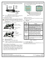

• Insert an antenna into the outside terminal on two of the antenna
connectors as shown in Figure 6. Tighten screws to secure the
antennas.
One Antenna
must mount
here and point
upwards.
Use one
of these
locations
for the
second
Antenna
Preferred
Location
(provides polar
diversity)
Figure 6- Connecting Antennas
Note: The remaining antenna connector and the remaining holes
in the used Antenna connectors are not used.
3.4 Setting Receiver Options
Changing these settings will require that the power to the
receiver be removed and then reapplied for the changes to
take effect. For more detailed information, refer to the
Wireless Reference Guide for the DS7400Xi Control/
Communicator.
• Set the Supervision Option as appropriate:
Supervision
Supervision = 2 Hours
Supervision = 12 Hours
Jumper left on pin for storage only.
(Default)
PWR BUS
+ - + -
ADDR
SUPV
Figure 7 - Supervision
• Set the Receiver Address Option as required:
This is Receiver # 1
(Default)
This is Receiver # 2
Address
Jumper left on pin for storage only.
PWR BUS
+ - + -
ADDR
SUPV
Figure 8 - Address
4.0
Wiring and Power Up
4.1
Wiring the Receiver to the Control Panel
Note: A DS7430 or a DS7436 Multiplex Module is required to
connect an RF3222E receiver to a DS7400Xi control panel.
• Disconnect power to the control panel.
• Connect the DS7430 or DS7436 Multiplex Module terminals to
the RF3222E receiver’s terminals as shown in Figure 9, using a
minimum diameter of 0.8 mm solid wire or 1.0 mm stranded wire.
Wire length between the receiver and the control panel should
not exceed 300 m. Adding additional devices to the bus may
reduce the maximum distance. Shielded cable is not
recommended. Do not use twisted pair wire.
• If using a DS7436 Multiplex Module, either bus block may be
used. If using two receivers and the DS7436 Multiplex Module,
either or both bus blocks may be used.
DS7430 or DS7436
Power Bus
PWR
BUS
RF3222E
+
-
+ -
+
-
+
-
Figure 9- Connecting to the Multiplex Bus
• Replace the outer cover.
• Apply power to the control panel. The red LED at the center of
the receiver should light.
4.2
LED Status
Table 1 describes the status of the receiver based on the LED
condition.
LED
Condition
Meaning
On
The receiver is functioning normally.
Off
A power failure has occurred or the receiver
is not wired correctly.
Turns Off
Momentarily
The receiver acknowledged receiving a
message from a compatible transmitter.
Flashes
Rapidly for
less than
1 minute
The receiver is being programmed with zone
and transmitter IDs from the compatible
panel. This condition will occur upon
initialization (power-up) of the system or
when new zone information has been
programmed into the system. The rapid
flashing should last for less than one minute.
Flashes
Rapidly for
more than
1 minute
The receiver has failed power-up self tests.
Replace receiver.
Table 1 - LED Status
5.0
Panel Programming
For programming information, refer to the Wireless Reference Guide
for the DS7400Xi Control/Communicator.
© 2004 Bosch Security Systems
130 Perinton Parkway, Fairport, New York, USA 14450-9199
Customer Service: (800) 289-0096; Technical Support: (888) 886-6189
03/04
RF3222E Installation Instructions
P/N: 41054D Page 2