Functional procedure
●
Only if both channels are activated "simultaneously" (by pressing one of
the enabling buttons), both output relays K1 and K2 will energize and the
output contacts 13-14 and 23-24 will close.
●
The output relays K1 and K2 will not energize if:
–
only one enabling channel was closed (in case of a defect).
–
the tolerance value for the simultaneity period is exceeded.
–
the feedback control loop S34 is open.
●
If one enabling channel is deactivated after being simultaneously activated
(by releasing the enabling button or in case of a defect), the output relays
K1 and K2 will return to their initial position again. The forced-guided out‐
put contacts 13-14 and 23-24 will open. The output relays will energize
again only after both enabling channels have been deactivated and closed
activated once again.
In this way the enabling switches avoid that one single error makes the safety
function inoperational. A single error will be recognized at the next cycle at the
latest, identifying that re-enabling is no longer possible. In case of short circuit
the monitoring device switches to "ERROR" state and has to be turned "OFF"
and "ON" again after resolving the error.
7.4.7
X3: Ethernet Interface
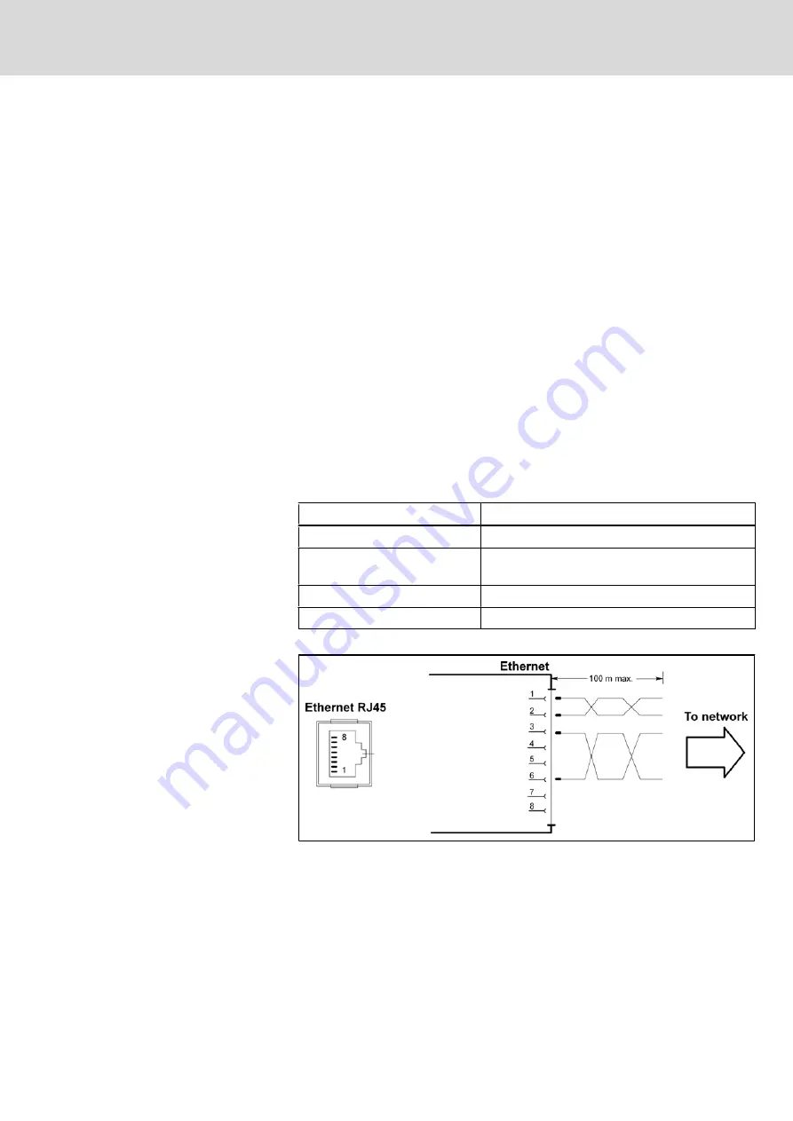
The embedded terminal can be connected to an Ethernet network via an
Ethernet interface.
RJ45, female connector, 8-pin
Type:
Ethernet 10Base T / 100Base X
Cable length:
Max. 65 m, category 6 patch cable (according to the
specifications) from VAC 30.2
Cable type:
Shielded, twisted pair
Transmission rate:
10 or 100 Mbits/s; class D
Fig.7-23:
Ethernet interface
Fig.7-24:
Pin assignment of the Ethernet interface X3
The configuration of the Ethernet interface is described more detailed in
7.5
Personality Function
Network connections VAC 30.2
connection module
In most cases the plant has a continuous Ethernet network. However, the as‐
signment of M-keys, stop button and enabling button is firmly assigned to one
control. The stop button and emergency stop button as well as the enabling
DOK-SUPPL*-VCH*08.1***-PR02-EN-P
Rexroth IndraControl VCH 08.1 Hand-held Terminal
Bosch Rexroth AG
85/117
Pin Assignments of the IndraControl VCH 08.1
Содержание Rexroth VCH 08.1
Страница 1: ...Electric Drives and Controls Pneumatics Service Linear Motion and Assembly Technologies Hydraulics ...
Страница 12: ...Bosch Rexroth AG DOK SUPPL VCH 08 1 PR02 EN P Rexroth IndraControl VCH 08 1 Hand held Terminal 10 117 ...
Страница 28: ...Bosch Rexroth AG DOK SUPPL VCH 08 1 PR02 EN P Rexroth IndraControl VCH 08 1 Hand held Terminal 26 117 ...
Страница 60: ...Bosch Rexroth AG DOK SUPPL VCH 08 1 PR02 EN P Rexroth IndraControl VCH 08 1 Hand held Terminal 58 117 ...
Страница 92: ...Bosch Rexroth AG DOK SUPPL VCH 08 1 PR02 EN P Rexroth IndraControl VCH 08 1 Hand held Terminal 90 117 ...
Страница 114: ...Bosch Rexroth AG DOK SUPPL VCH 08 1 PR02 EN P Rexroth IndraControl VCH 08 1 Hand held Terminal 112 117 ...
Страница 118: ...Bosch Rexroth AG DOK SUPPL VCH 08 1 PR02 EN P Rexroth IndraControl VCH 08 1 Hand held Terminal 116 117 ...
Страница 119: ...Notes DOK SUPPL VCH 08 1 PR02 EN P Rexroth IndraControl VCH 08 1 Hand held Terminal Bosch Rexroth AG 117 117 ...


