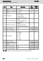
7.10.7 Sensor Monitoring
Code
Name
Setting range
Default
Attri.
F2.16 X1 input
0: No function assigned from ASF
1: Pressure command selection bit0
2: Pressure command selection bit1
3: p/Q parameter set selection
4: Flow command selection
5: Master / slave mode switch
6: Oil filter warning
7: Oil level warning
8: Oil temperature warning
9: Oil filter error
10: Oil level error
11: Oil temperature error
12: Oil level / temperature error
13: Oil filter warning inverse
14: Oil level warning inverse
15: Oil filter error inverse
16: Oil level / temperature error inverse
17: Reserved
18: Reserved
19: Reserved
20: Pressure drop compensation trigger
21: Pressure overshoot compensation
trigger
22: Drive enable for myCro
-
Stop
F2.17 X2 input
Stop
F2.18 X3 input
Stop
F2.19 X4 input
Stop
F2.20 X5 input
Stop
F2.21 EX1 input
Stop
F2.22 EX2 input
Stop
F2.23 EX3 input
Stop
F2.24 EX4 input
Stop
F2.25 EX5 input
Stop
Tab. 7-26: Parameter list of sensor monitoring
There are different sensors used for monitoring the hydraulic system, and there
are also corresponding options for digital input to be selected, see option 6...16
in the table above. Most of these options can be clarified by name, the others
are described below:
''6: Oil filter warning'' and ''9: Oil filter error'' for oil filter warning and error sen-
sor. These signals will be automatically delayed by F4.50, that means a true sig-
nal lasted longer than [F4.50] seconds will be acknowledged.
''12: Oil level / temperature error'', for oil level and temperature error sensor.
Both oil level and temperature can be connected parallel to one digital input,
since oil warning comes earlier than error, the warning information will help con-
Bosch Rexroth AG
Block Diagram of Main Functions
FcP 5020
52/83
DOK-RCON03-FCP5020****-QU04-EN-P


