
▶ Mount in a dry, dust-free environment.
▶ Ensure that the contact surface on the machine side is burr-free.
▶ Securely screw the motor-pump unit onto the machine construc-
tion.
Choose a fastening variant N, A or B according to the machine config-
uration.
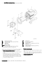
Install motor-pump unit MPA01 on system
Fastening variant
Hole
ø [mm]
Screw
Washer
A
Foot fastening without damping rails 12
M10
yes
Foot fastening with damping rails
B
Foot fastening flange
18
M16
yes
N
Flange fastening
18
M16
yes
MPA01 fastening accessory
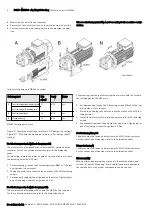
Figure "A" shows the mounting of motors in "SA" design (air cooling).
Figure “B”, “N” shows the mouning of motors in "FN" design (liquid
cooling).
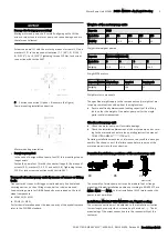
Foot fastening motor A (without damping rails)
The motor must be fastenend with screws (4xM10) provided by the
customer. For the connection dimensions refer to the dimension
sheet.
For mounting, remove the lower air guide of motors with fan to reach
the fastening holes (4x Ø12 mm).
1. For dismounting, loosen the 3 fastening screws M5x12 of the low-
er air guides (cross recess).
2. Fasten the motor onto the machine by means of 4x M10 fastening
screws.
3. Subsequently remount the air guides on the motor. Tightening tor-
que of fastening screws of air guides 6.1 Nm.
Foot fastening motor A (with damping rails).
The motor must be fastened with screws (4x M10) by the customer.
For the connection dimensions refer to the dimension sheet.
For mounting, remove the lower air guide of motors with fan to reach
the fastening holes (4x Ø12 mm).
1. For dismounting, loosen the 3 fastening screws M5x12 of the low-
er air guides (cross recess).
2. Fasten the damping rails onto the motor by means of 4x M10 fas-
tening screws.
3. Fasten the motor onto the machine by means of 4x M10 fastening
screws.
4. Subsequently remount the air guides on the motor. Tightening tor-
que of fastening screws of air guides 6.1 Nm.
Foot fastening flange B
The motor must be fastened with screws (4x M16) by the customer.
For the connection dimensions refer to the dimension sheet.
Flange fastening N
The motor must be fastened with screws (4x M16) by the customer.
For the connection dimensions refer to the dimension sheet.
Disassembly
When performing disassembly, proceed in the reverse order as de-
scribed in Chapter "Mounting". Work carefully and avoid damage to
the components. Only proper components can be re-used.
4
PGH5 - MSK133 - Air / Liquid Cooling | Motor-Pump Unit MPA01
Bosch Rexroth AG, Edition 03 , R911341600, DOK-SYTROX-MPA01*M13**-AS03-EN-P