22
/84
Bosch Rexroth AG
LTU350/1 | 3 609 929 B47/2008-12
Language packs
The language pack for the LTU350/1 is
uploaded to the controller using the BS350
operating program. This is done via the menu
item “Configuration | HMI SE/CS” in the
BS350.
LED display and reset button
There are three LEDs on the front panel of the
servo amplifier to indicate the operating
state.
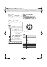
XDS1 interface for handheld
nutrunner
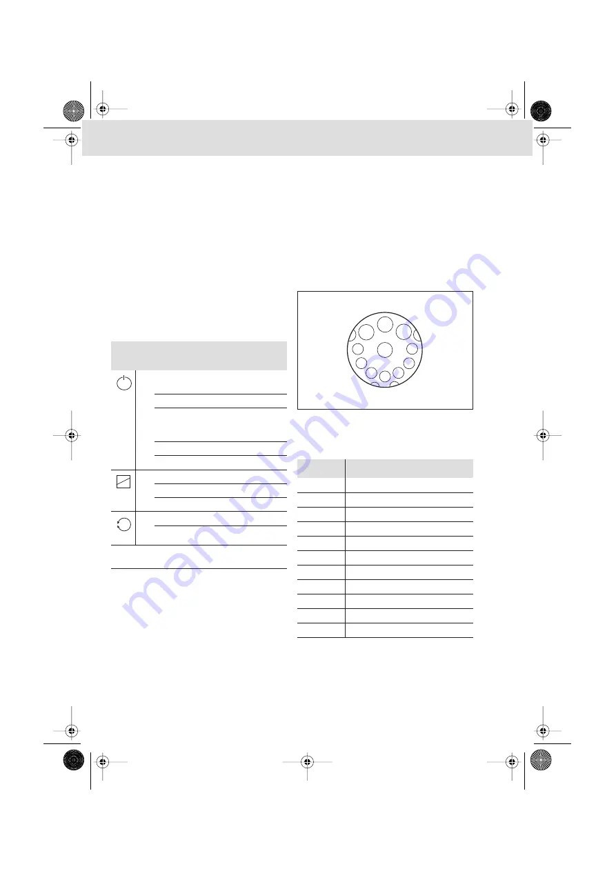
The tightening spindle is connected to the
servo amplifier via a spindle connecting cable
that is connected to the 11-pin socket. The
power supply for the motor, logic supply, and
transmission of interface signals is provided
via this cable.
Fig. 3: Socket, view from front side
Table 5
LED/
button
Display Diagnosis
BTB
Off
No power supply or LTU is in
download mode
Green
Ready for operation
Green,
flashing
Not ready for operation, but
no system error; emergency
OFF has been triggered
Red
System error
Orange
VM supply module not ready
TS
Off
Motor contactor open
Green
Ready for operation
Red
Motor contactor error
FG
Off
No servo amplifier release
Green
Servo amplifier release
Reset
When pressed, a reset is performed to
reinitialise the tightening channel
Table 6
Pin
Signal assignment
1
CAN-L
2
CAN-H
3 24
V
4 GND
5 HS
6 SAMI-B
7 SAMI-A
U
Phase U
V
Phase V
A
Phase W
PE
Protective earth/shield
V
1
2
3
4
5
6
7
PE
U
A
∆
LTU350.book Page 22 Tuesday, December 16, 2008 12:24 PM


