7.1.5
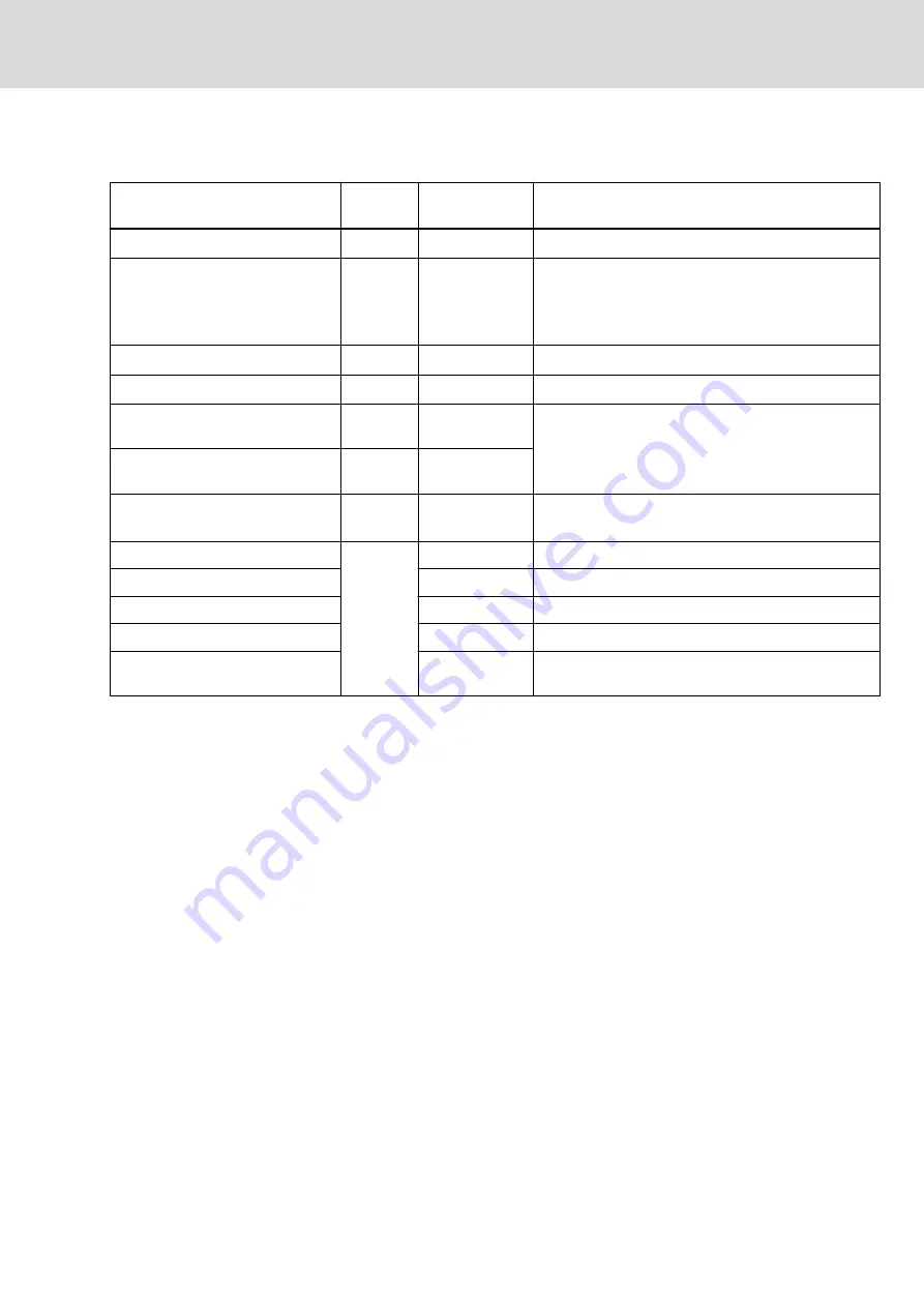
Control voltage power requirement 42 V
Power components
Symbol
Power require‐
ment [W]
Explanation
Basic power of the component
P
Basic
15
Component: KSM, KMS, KMV, …
Digital inputs/outputs
P
IO
2.5
Connection point X37, X38
The power component is only available when the digi‐
tal outputs are used without an additional external 24V
supply.
Optional safety technology S3
P
S3
2.5
Safety option "Safe Motion (without SBC)"
Optional safety technology SD
P
SD
2.5
Safety option "Safe Motion"
Optional master communication
output coupling TO
P
TO
-
No additional power required
Optional external master communi‐
cation ES
P
ES
-
Optional safety technology L3
P
L3
n.s.
Power requirement contained in basic power of the
component P
Basic
Motor holding brake KSM…041
P
Br
12
Motor holding brake KSM…061
18
Motor holding brake KSM…071
24
Motor holding brake KSM…076
24
Motor holding brake KMS
n.s.
See specification of motor holding brake of the con‐
nected motor
Tab. 7-1:
Control voltage power requirement
Control voltage power requirement
of one component
P
N3_42V
= P
Basic
+ P
IO
+ P
S3/SD
+ P
Br
Control voltage power requirement
of multiple components of a drive
line
P
total
= ΣP
N3_42V
DOK-INDRV*-KCU02+KSM02-PR03-EN-P
Bosch Rexroth AG
197/337
Rexroth IndraDrive Mi Drive Systems with KCU02 KSM02, KMS02/03, KMV03, KNK03
Notes on project planning
LSA Control S.L. www.lsa-control.com [email protected] (+34) 960 62 43 01


