Death or serious injury caused by wrong han-
dling!
WARNING
●
The E-STOP button can be used as operating element in an E-STOP circuit
●
The E-STOP circuit has to be designed by the machine manufacturer
●
Only qualified staff may connect the E-STOP button and check it afterwards
●
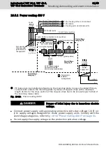
Make the connection according to the connection scheme in
pad connection diagram" on page 32
●
The max. load current is 500 mA
For further information on the E-STOP button, please refer to
STOP button (VEP30.6)" on page 10
chapter 8.1 "E-STOP button – Stand-
.
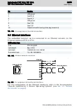
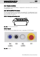
Pin assignment of the keypad
Pin
Function
1
S1 (E-STOP) N/C contact 1
2
S1 (E-STOP) N/C contact 1
3
S1 (E-STOP) N/C contact 2
4
S1 (E-STOP) N/C contact 2
5
S2 (white key), N/O contact / N/C contact
6
S2 (white key) N/O contact
7
S2 (white key) N/C contact
8
S3 (black key), N/O contact / N/C contact
9
S3 (black key) N/O contact
10
S3 (black key) N/C contact
Tab. 10-5: Pin assignment of the keypad, plug X3
Pin
Function
1
S4 (blue key), N/O contact / N/C contact
2
S4 (blue key) N/O contact
3
S4 (blue key) N/C contact
4
LED2 in S2 (white key) +24V
5
LED4 in S4 (blue key) +24 V
6
LED2/LED4 -0V
Tab. 10-6: Pin assignment of the keypad, plug X2
IndraControl VEP 30.6, VEP 40.6,
VEP 50.6 Embedded Terminals
33/49
Mounting, demounting and electric installation
R911403058_Edition 01 Bosch Rexroth AG
Содержание rexroth IndraControl VEP 30.6
Страница 6: ...IV IndraControl VEP 30 6 VEP 40 6 VEP 50 6 Embedded Terminals Bosch Rexroth AG R911403058_Edition 01 ...
Страница 52: ...46 49 IndraControl VEP 30 6 VEP 40 6 VEP 50 6 Embedded Terminals Bosch Rexroth AG R911403058_Edition 01 ...
Страница 55: ...Notes IndraControl VEP 30 6 VEP 40 6 VEP 50 6 Embedded Terminals 49 49 ...

