5.2
Electric installation
5.2.1
General information
Electric shock and unintended machine start‐
up due to installation works without to ensure
that there is no voltage applied.
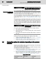
WARNING
●
Disconnect the complete system from the voltage before performing in‐
stallation works and secure the system against unintended voltage ap‐
plication.
●
Connect the voltage only after the setting is complete and ensure that
there is no hazard originating from the station or the system. Observe
the diagnostic displays and possible diagnostic messages.
5.2.2
Electric installation of the IndraControl S20 station
For the electric installation of the IndraControl S20 station, proceed as fol‐
lows:
●
Connection to the parent bus system
●
Connection of the supply voltages for the IndraControl S20 station
Perform the electric installation of the IndraControl S20 station as described
in the following manuals:
●
Application description of the IndraControl S20 system
●
Sercos system manual for I/O devices
Observe the additional information in the documentation of the bus coupler.
5.2.3
Electric installation of the module
Observe the general safety instructions, refer to
"Safety of machine or system" on page 8
.
Loss of the safety function as well as material
damage due to an incorrect installation.
WARNING
●
Take measures against exchanging or reversing the polarity of connec‐
tions.
●
Impede manipulations at the connections.
The voltage supply for the module electronics is fed in at the bus coupler.
From there, the supply voltage of the module logic is provided via the bus
base module. The supply voltage of the output circuits is directly fed in at the
module.
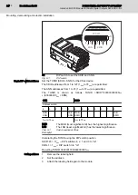
The actuators are connected via the IndraControl S20 plug.
Wire the connectors according to their application, refer to
signing terminal points" on page 12
DOK-CONTRL-S20*SSDO*8*-AP02-EN-P
Bosch Rexroth AG
27/85
IndraControl S20 Module With Safe Digital Outputs S20-SSDO-8/3
Mounting, demounting and electric installation

