


Installation 51/104
RE 92076-01-B/10.2017, A4... with HS5E pilot control valve/Series 3x,
Bosch Rexroth AG
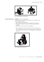
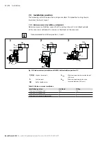
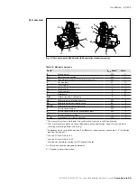
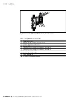
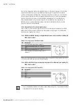
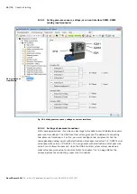
Fig. 16: Port overview of A4VSO with HS5E controller, clockwise rotation
Table 12: A4V ports Series 3x
Ports
1)
p
max
[bar]
2)
State
B
Working port
400
O
B
1
4)
Additional connection
400
O
B
1
5)
Second pressure port (high-pressure series)
400
O
S
Suction port
30
O
K
1
Flushing port
4
X
K
2
Flushing port
4
X
U
Flushing port
4
O
6)
T
Fluid drain
4
X
3)
R(L)
Fluid filling and air bleeding
4
O
3)
M
B
Measuring port working pressure
400
X
M
S
Measuring port suction pressure
30
X
M
1
, M
2
Measuring port control pressure
400
X
P
Control pressure port
350
X
S
p
Control pressure port of accumulator port
350
X
R
KV
Control fluid return flow
5
X
R
2
- R
7
Air bleeding of stroking chamber
350
X
1)
The measuring system and thread size can be taken from the installation drawing.
2)
Short-term pressure peaks may occur depending on the application. Keep this in mind when
selecting measuring devices and fittings.
3)
Depending on the installation position,
T
or
R
(
L
) must be connected (see chapter 7.3 “Installation
4)
Version 13: for NG 40 to 355
5)
Version 25: for NG 40 to 1000
6)
Must be connected for version for HFC hydraulic fluids.
O = Must be connected (plugged on delivery)
X = Plugged (in normal operation)
Port overview
S
T
M
S
K
1
R(L)
U
K
2
B
B
1
R
5
-
R
7
R
2
-
R
4
R
KV
S
P
M
2
M
1
P
M
B
M
B