44/64 Installation
Bosch Rexroth AG
, Series 10 A10VG, RE 92750-01-B/06.2018
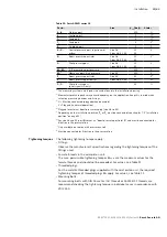
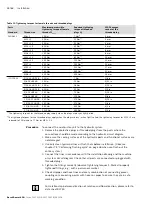
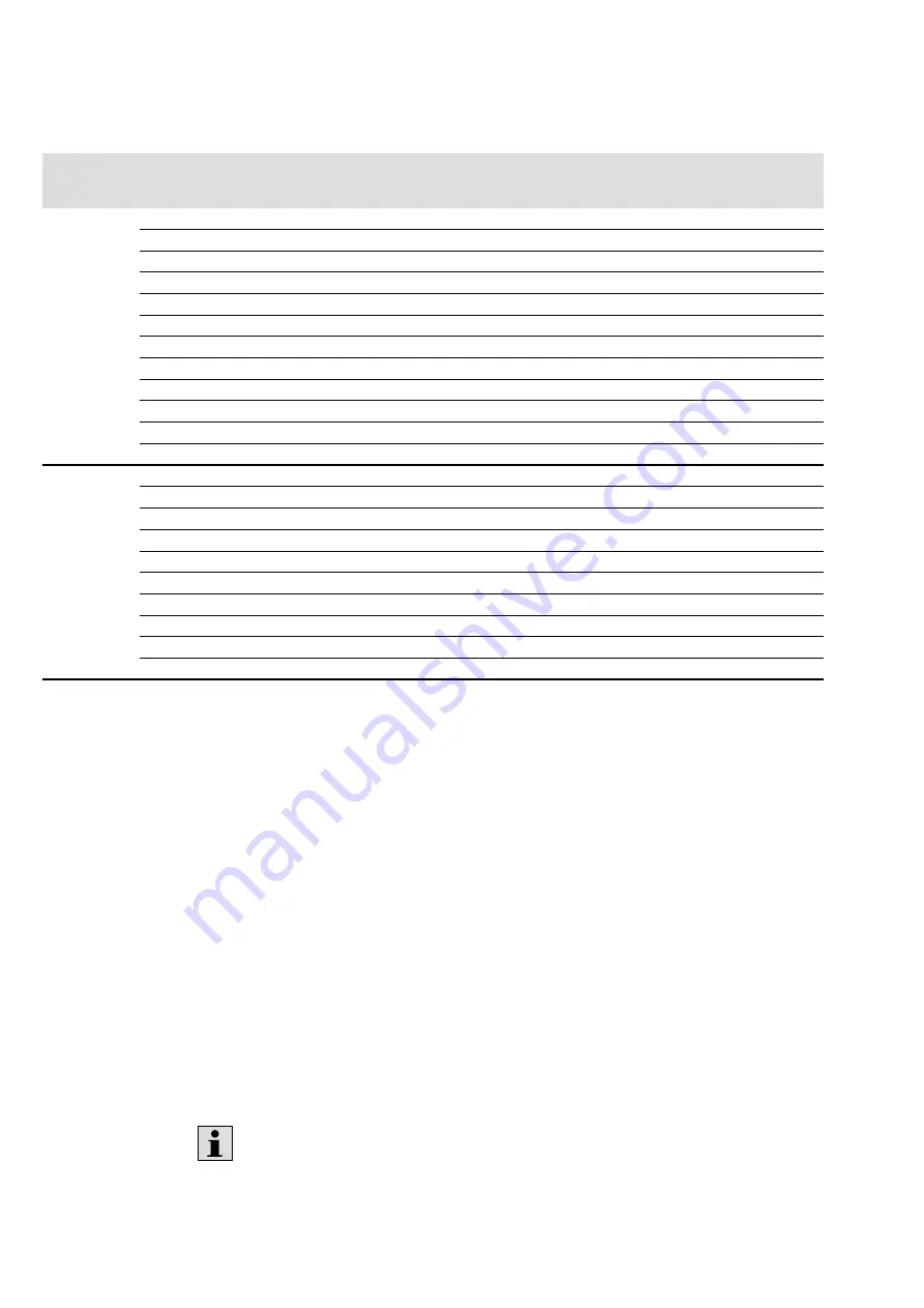
Table 11: Tightening torques for female threads and threaded plugs
Ports
Maximum permissible
tightening torque of female
threads
M
G max
Required tightening
torque of threaded
plugs
M
V
wAF hexagon
socket of the
threaded plug
Standard
Thread size
DIN 3852
M8 × 1
10 Nm
7 Nm
1)
3 mm
M10 × 1
30 Nm
15 Nm
2)
5 mm
M12 × 1.5
50 Nm
25 Nm
2)
6 mm
M14 × 1.5
80 Nm
35 Nm
1)
6 mm
M16 × 1.5
100 Nm
50 Nm
1)
8 mm
M18 × 1.5
140 Nm
60 Nm
1)
8 mm
M22 × 1.5
210 Nm
80 Nm
1)
10 mm
M26 × 1.5
230 Nm
120 Nm
1)
12 mm
M27 × 2
330 Nm
135 Nm
1)
12 mm
M33 × 2
540 Nm
225 Nm
1)
17 mm
M42 × 2
720 Nm
360 Nm
1)
22 mm
M48 × 2
900 Nm
400 Nm
1)
24 mm
ISO 11926
5/16-24 UNF-2B
10 Nm
7 Nm
1/8 in
3/8-24 UNF-2B
20 Nm
10 Nm
5/32 in
7/16-20 UNF-2B
40 Nm
18 Nm
3/16 in
9/16-18 UNF-2B
80 Nm
35 Nm
1/4 in
3/4-16 UNF-2B
160 Nm
70 Nm
5/16 in
7/8-14 UNF-2B
240 Nm
110 Nm
3/8 in
1 1/16-12 UN-2B
360 Nm
170 Nm
9/16 in
1 5/16-12 UN-2B
540 Nm
270 Nm
5/8 in
1 5/8-12 UN-2B
960 Nm
320 Nm
3/4 in
1 7/8-12 UN-2B
1200 Nm
390 Nm
3/4 in
1)
The tightening torques for the threaded plugs apply when the plugs are dry or lightly oiled.
2
The tightening torques for the threaded plugs apply when the plugs are dry – when lightly oiled, the tightening torques for M10 × 1 are
reduced to 10 Nm and to 17 Nm for M12 × 1.5.
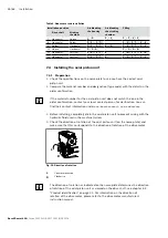
To connect the axial piston unit to the hydraulic system:
1.
Remove the protective plugs or threaded plugs from the ports where the
connections should be made according to the hydraulic circuit diagram.
2.
Make sure the sealing surfaces of the hydraulic ports and functional surfaces are
not damaged.
3.
Use only clean hydraulic lines or flush them before installation. (Observe
chapter 7.5 “Performing flushing cycle” on page 46 when you flush out the
entire system.)
4.
Connect the lines in accordance with the installation drawing and the machine
or system circuit diagram. Check that all ports are connected or plugged with
threaded plugs.
5.
Tighten the fittings correctly (observe tightening torques!). Mark all properly
tightened fittings, e.g., with a permanent marker.
6.
Check all pipes and hose lines and every combination of connecting pieces,
couplings or connecting points with hoses or pipes to ensure they are in safe
working condition.
For relationship between direction of rotation and flow direction, please refer to
data sheet 92750.
Procedure

