background image

34/56 Installation

Bosch Rexroth AG

, A10VER Series 52, RE 91706-01-B/09.2015

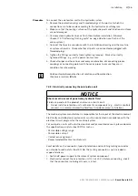
Connect only hydraulic lines that are appropriate for the axial piston unit port 
(pressure level, size, system of units).

Observe the following notes when routing the pressure and drain lines.


Lines and hoses must be installed without pre-charge pressure, so that no further 
mechanical forces are applied during operation that will reduce the service life of 
the axial piston unit and, if applicable, the entire machine/system. 


Use suitable seals as sealing material.


Pressure line


– For the pressure lines, use only pipes, hoses and connecting elements rated for 

the working pressure range specified in data sheet 91706 (see Table 10).


Drain line


– Always route the drain lines so that the case is constantly filled with hydraulic 

fluid and to ensure that no air gets through the shaft seal even during extended 
standstill periods.


– Under no operating circumstances may the case pressure exceed the maximum 

values specified for the axial piston unit in the data sheet.


– The drain line joint in the reservoir must always be below the minimum fluid level 

(see Chapter 7.3 “Installation position” on page 28).


If the axial piston unit is equipped with installed screw fittings, these must not be 
unscrewed. Screw the stud end of the fitting directly into the installed screw fitting.

Axial piston units are employed in regions using the metric measuring system, in 
regions using the Anglo-American (imperial) measuring system and in regions using 
the Japanese measuring system (JIS – 

J

apan 

I

ndustrial 

S

tandard). Moreover, various 

kinds of seal are used.
The system of units, the kind of seal and the size of female thread and stud ends 
(e.g., threaded plug) must all match.
The limited ways of telling them apart visually poses a risk of confusing them.

wARnInG.

 Leaky or bursting stud ends.

For fittings, if a stud end which is of a different measurement system, kind of seal and 
size with respect to the female thread is pressurized, the stud end may loosen itself 
or even be ejected from the hole in a projectile-like manner. This can result in serious 
injury and property damage. Hydraulic fluid can escape from this leakage point.


Use the drawings (installation drawing) to determine the required stud end for 
each fitting.


Make sure the right fittings, mounting bolts and threaded plugs are installed.


For all female threads, use a stud end from the same system of units and of the 
correct size.

notes on routing lines

Risk of confusion with 

threaded connections

Содержание Rexroth A10VER 52 Series

Страница 1: ...lace this illustration area with an illustration of your product Instruction manual RE 91706 01 B 09 2015 Replaces English Reversible A10VER Axial piston variable motor for hydrostatic fan drives Series 52 ...

Страница 2: ... from the obligation of own judgment and verification It must be remembered that our products are subject to a natural process of wear and aging This document as well as the data specifications and other information set forth in it are the exclusive property of Bosch Rexroth AG It may not be reproduced or given to third parties without consent The cover shows an example application The product del...

Страница 3: ...oduct description 20 5 2 1 Layout of the axial piston unit 20 5 2 2 Functional description 21 5 3 Product identification 22 6 Transport and storage 23 6 1 Transporting the axial piston unit 23 6 1 1 Transporting by hand 23 6 1 2 Transporting with a lifting device 23 6 2 Storing the axial piston unit 25 7 Installation 27 7 1 Unpacking 27 7 2 Installation conditions 27 7 3 Installation position 28 7...

Страница 4: ... 42 9 Operation 43 10 Maintenance and repair 44 10 1 Cleaning and care 44 10 2 Inspection 44 10 3 Maintenance 45 10 4 Repair 45 10 5 Spare parts 46 11 Removal and replacement 47 11 1 Required tools 47 11 2 Preparing for removal 47 11 3 Performing removal 47 11 4 Preparing the components for storage or later use 47 12 Disposal 48 13 Extension and conversion 49 14 Troubleshooting 50 14 1 How to proc...

Страница 5: ... for your A10VER axial piston variable motor Order confirmation Installation drawing Contains the outer dimensions all connections and the hydraulic circuit diagram for your A10VER axial piston variable motor Please request the installation drawing from your contact at Bosch Rexroth Installation drawing Axial Piston Plug In Motor A10VER Contains the permissible technical data 91706 Data sheet Proj...
Страница 6: ... to property and the product on page 16 and before a sequence of actions or an instruction for action involving a risk of personal injury or damage to equipment The described danger prevention measures must be observed Safety instructions are set out as follows Signal word Type and source of danger Consequences of noncompliance Measures to prevent danger Warning sign draws attention to the danger ...

Страница 7: ...circuit for hydrostatic fan drives Threaded plug Metal screw pressure resistant Protection plug Made out of plastic not pressure resistant only for transportation The designation axial piston unit or hydraulic motor is used hereafter as a generic term for A10VER plug in axial piston motor 1 3 4 Abbreviations This documentation uses the following abbreviations Table 5 Abbreviations Abbreviation Mea...

Страница 8: ...for which it is intended and the safety of the entire system has been established in accordance with the machinery directive This product is intended for the following use The axial piston unit is designed solely as a hydraulic motor in hydrostatic fan drives in open circuit Observe the technical data the application and operating conditions and the performance limits as specified in data sheet 91...

Страница 9: ...craft 2 4 Personnel qualifications The activities described in this documentation require basic mechanical electrical and hydraulics expertise as well as knowledge of the associated technical terms For transporting and handling the product additional knowledge is necessary with regard to working with lifting devices and their slings In order to ensure safe use these activities should only be perfo...

Страница 10: ...in the product documentation for example in explosion protection applications or in safety related parts of a control system functional safety You may only commission the product if it has been determined that the end product e g machinery or system in which the Rexroth products are installed complies with the country specific provisions safety regulations and standards for the application Use too...

Страница 11: ...ad to injuries e g crushing or broken bones or damage to the product Make sure that the load bearing capacity of the lifting gear is sufficient to safely bear the weight of the axial piston unit Never stand or put your hands under a suspended load Make sure the unit remains stable during transport Wear your personal protective equipment e g safety goggles safety gloves suitable working clothes saf...

Страница 12: ...s the fan wheel to run at maximum speed Check whether or not your machine requires additional safety measures for your application Fan wheel stationary while machine is running Risk of death or injury from sudden fan wheel movement Never reach into the machine while it is running e g to get the fan wheel to move Use reversing to attempt to get the fan wheel to move again See also the required oper...

Страница 13: ...chine system so that it is free of electrical voltage before you install the product or when connecting and disconnecting connectors Protect the machine system against being re energized Restriction of the control function Risk of injury or property damage Moving parts in control equipment e g valve spools can under certain circumstances get blocked in position as a result of contamination e g imp...

Страница 14: ...t no one can trip over them that they do not become kinked or twisted do not rub on edges and do not run without adequate protection from sharp edged ducts Contact with hydraulic fluid Inhalation may result in health hazards or adverse health effects including eye injuries skin irritation and poisoning Avoid contact with hydraulic fluids When working with hydraulic fluids strictly observe the safe...

Страница 15: ...52 Bosch Rexroth AG 2 7 Personal protective equipment Personal protective equipment is the responsibility of the user of the axial piston unit Observe the safety regulations and provisions in your country All pieces of personal protective equipment must be intact ...

Страница 16: ... g during painting operations Risk of property damage due to improper lubrication Product can be damaged or destroyed Never operate the axial piston unit with insufficient hydraulic fluid Specifically make sure that the rotary group has sufficient lubrication When commissioning a machine system make sure that the housing area and the working lines of the axial piston unit are filled with hydraulic...

Страница 17: ...imize solid impurities and water in the hydraulic system Improper cleaning Product can be damaged Plug all openings with the appropriate protection equipment in order to prevent cleaning agents from entering the hydraulic system Never use solvents or corrosive cleaning agents Use only water and if necessary a mild cleaning agent to clean the axial piston unit Do not point the high pressure cleaner...

Страница 18: ...specifications provided by the system manufacturer Danger from hot components Nearby products can be damaged Components which heat up e g solenoids can cause damage to nearby products if they are too close When installing the axial piston unit check the distances to nearby products to ensure that they are not damaged The warranty only applies to the delivered configuration The warranty is void in ...

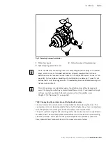
Страница 19: ...Scope of delivery 2 3 1 Fig 1 Axial piston unit The following is included in the scope of delivery Axial piston unit as per order confirmation The following parts are also assembled prior to delivery Protective covers 1 Protective plug threaded plug 2 Solenoid plug protective cover 3 ...

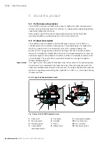
Страница 20: ...he drive shaft 1 The pistons place a load on the swashplate cradle 9 and transfer the torque dependent on pressure and swivel angle via the cylinder to the drive shaft 6 The cylinder and drive shaft are interlocked The control of the swashplate cradle can change the specific torque and displacement In an open circuit the hydraulic fluid flows from the reservoir to the hydraulic pump from where it ...

Страница 21: ...displacement The output speed is proportional to the inward flow and inversely proportional to the displacement of the hydraulic motor The swivel angle of the swashplate cradle 9 is switchable from 100 to 100 EZ two point control Control of the swivel angle of the swashplate changes the piston stroke and therefore the displacement The neutral position also changes the hydraulic motor s direction o...

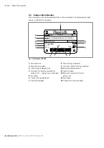
Страница 22: ... MNR FD Rexroth A10VER45EZ6 52R VCF10N002P 11W20 1 5 2 3 4 9 10 11 12 6 7 8 13 14 Fig 3 Name plate A10VER 1 Manufacturer 2 Manufacturing date 3 Internal plant designation 4 Direction of rotation viewed on drive shaft shown here clockwise 5 Bar code 6 Power setting optional 7 Rotational speed 8 Flow setting optional 9 Pressure control setting optional 10 Minimum displacement 11 Serial number 12 Mat...

Страница 23: ...to 15 kg can be transported manually for a short time if necessary Caution Danger from heavy loads Health hazard from carrying axial piston units Use suitable lifting lowering and moving methods Wear your personal protective equipment e g safety goggles safety gloves suitable working clothes safety shoes Do not use sensitive attachments to transport the axial piston unit e g sensors or valves Care...

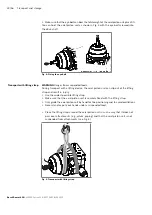
Страница 24: ...iston unit can slip out of the lifting strap and result in injury Use the widest possible lifting strap Make sure that the axial piston unit is securely fixed with the lifting strap Only guide the axial piston unit by hand for fine positioning and to avoid oscillations Never stand or put your hands under a suspended load Place the lifting strap around the axial piston unit in such a way that it do...

Страница 25: ...storage times for an originally packed axial piston unit as per data sheet 90312 Table 7 Storage time with factory corrosion protection Storage conditions Standard corrosion protection Long term corrosion protection Closed dry room at a consistent temperature between 5 C and 20 C throughout Undamaged and sealed corrosion protection film Maximum 12 months Maximum 24 months Warranty is void if the r...

Страница 26: ...page 44 2 Empty the axial piston unit 3 For storage periods up to 12 months Coat the inside of the axial piston unit with mineral oil and fill with approx 100 ml mineral oil For storage periods up to 24 months Fill the axial piston unit with VCI 329 corrosion protection 20 ml Filling is performed via drain port L see Chapter 7 4 Installing the axial piston unit Fig 10 on page 35 4 Seal all ports s...

Страница 27: ... see Chapter 4 Scope of delivery on page 19 Dispose of the packaging material according to the national regulations in your country 7 2 Installation conditions The installation location and position of the axial piston unit essentially determine the procedures during installation and commissioning such as when filling and air bleeding the axial piston unit Fix the axial piston unit so that the exp...

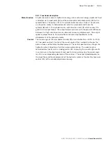
Страница 28: ... remove lubricants and other difficult to remove contamination Cleaning agents must not enter the hydraulic system 7 3 Installation position The following installation positions are permissible The piping layout shown illustrates the basic layout 7 3 1 Below reservoir installation standard Below reservoir installation is when the axial piston unit is installed outside of the reservoir and below th...

Страница 29: ... 4 Fig 7 Above reservoir installation A10VER with installation position 3 4 L Highest drain port ht min Minimum required immersion depth 200 mm F Filling air bleeding hmin Minimum required distance to reservoir bottom 100 mm Port F is part of the external piping and must be provided by the customer to make filling and air bleeding easier Table 9 Above reservoir installation Installation position A...

Страница 30: ...tion of rotation of the axial piston unit on the name plate and make sure that this corresponds to the direction of rotation of the intended motor function L R Fig 8 Direction of rotation R Clockwise cooling operation counter clockwise reversing operation L Counter clockwise upon request counter clockwise cooling operation clockwise reversing operation The direction of rotation as specified on the...

Страница 31: ...riking it 1 Install the specified coupling half onto the drive shaft of the axial piston unit according to the instructions of the coupling manufacturer The drive shaft of the axial piston unit is equipped with a female thread Use this female thread to pull the coupling element onto the drive shaft The size of the female thread can be seen in the installation drawing 2 Clamp the coupling hub onto ...

Страница 32: ...ow enough space for the cardan shaft to fit through on both sides 2 Join the cardan shaft to the drive shaft of the machine system 3 Push the axial piston unit to the cardan shaft and join the cardan shaft to the output shaft of the axial piston unit 4 Bring the axial piston unit to the installation position and secure If necessary details on the required tools and tightening torque for the mounti...

Страница 33: ... protected against unintentional resetting by means of caps Changing the adjusting screw will void the warranty If you need to change settings contact your Bosch Rexroth service partner for address see Chapter 10 5 Spare parts on page 46 7 4 8 Connecting the axial piston unit to hydraulic system The machine system manufacturer is responsible for dimensioning the lines The axial piston unit must be...

Страница 34: ...tion on page 28 If the axial piston unit is equipped with installed screw fittings these must not be unscrewed Screw the stud end of the fitting directly into the installed screw fitting Axial piston units are employed in regions using the metric measuring system in regions using the Anglo American imperial measuring system and in regions using the Japanese measuring system JIS Japan Industrial St...

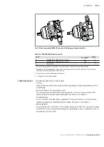
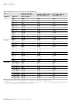
Страница 35: ...ed on delivery X Plugged in normal operation The following tightening torques apply Fittings Observe the manufacturer s specifications regarding the tightening torques of the used fittings Female threads in the axial piston unit The maximum permissible tightening torques MG max are maximum values of the female threads and must not be exceeded For values see Table 11 Threaded plugs For the metallic...

Страница 36: ... M12 1 5 50 Nm 25 Nm2 6 mm M14 1 5 80 Nm 35 Nm1 6 mm M16 1 5 100 Nm 50 Nm1 8 mm M18 1 5 140 Nm 60 Nm1 8 mm M22 1 5 210 Nm 80 Nm1 10 mm M26 1 5 230 Nm 120 Nm1 12 mm M27 2 330 Nm 135 Nm1 12 mm M33 2 540 Nm 225 Nm1 17 mm M42 2 720 Nm 360 Nm1 22 mm M48 2 900 Nm 400 Nm1 24 mm ISO 11926 5 16 24 UNF 2B 10 Nm 7 Nm 1 8 in 3 8 24 UNF 2B 20 Nm 10 Nm 5 32 in 7 16 20 UNF 2B 40 Nm 18 Nm 3 16 in 9 16 18 UNF 2B 8...

Страница 37: ...n direction of rotation and flow direction Clockwise rotation B to A 7 4 9 Electrically connecting the axial piston unit NOTICE Short circuit in event of penetrating hydraulic fluid Fluid can penetrate the product and cause a short circuit Do not install axial piston units with electric components e g electric controls sensors in a reservoir below the fluid level inside reservoir installation The ...

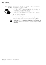
Страница 38: ... desired orientation 3 Retighten the mounting nut Tightening torque of the mounting nut 5 1 Nm 7 5 Performing flushing cycle In order to remove foreign particles from the system Bosch Rexroth recommends a flushing cycle for the entire system before the first commissioning To avoid internal contamination the axial piston unit must not be included in the flushing cycle The flushing cycle must be per...

Страница 39: ... Chapter 2 Safety instructions on page 8 and specifically project planning and commissioning instructions 90363 Connect the gauge for the working pressure and case pressure to the specified measuring points on the axial piston unit or in the hydraulic system to check the technical data at first operation During the commissioning process monitor the temperature of the hydraulic fluid in the reservo...

Страница 40: ...e axial piston unit can only be started when the shut off valves are open 3 When using a shut off valve in the drain line only operate the axial piston unit when the shut off valves are open 8 1 2 Testing the hydraulic fluid supply The axial piston unit must always have a sufficient supply of hydraulic fluid For this reason the supply of hydraulic fluid must be ensured at the start of the commissi...

Страница 41: ...ified pressures e g working pressure and case pressure Perform a leak test without and with load prior to normal operation If necessary disconnect the pressure gauge and plug the ports with the designated threaded plugs 8 2 Running in phase NOTICE Property damage from insufficient viscosity An increased hydraulic fluid temperature may reduce the viscosity values by too much and damage the product ...

Страница 42: ...required cleanliness level is not reached If a laboratory test is not carried out after the running in phase it is recommended to change the hydraulic fluid 8 3 Recommissioning after standstill Depending on the installation conditions and ambient conditions changes may occur in the hydraulic system which make recommissioning necessary Among others the following criteria may make recommissioning ne...

Страница 43: ...ttings or changes during operation For this reason this chapter of the manual does not contain any information on adjustment options Use the product only within the performance range specified in the technical data The machine system manufacturer is responsible for the proper project planning of the hydraulic system and its control ...

Страница 44: ...a mild cleaning agent to clean the axial piston unit Never use solvents or corrosive cleaning agents Remove major external contamination and keep sensitive and important components such as solenoids valves and sensors clean 10 2 Inspection In order for the axial piston unit to be reliable and long lasting Bosch Rexroth recommends testing the hydraulic system and axial piston unit on a regular basi...

Страница 45: ...acturer or a laboratory to determine its suitability for further use The service life of the axial piston unit is limited by the service life of the bearings used The service life on the basis of the load cycle can be requested from the proper Bosch Rexroth service partner see Chapter 10 5 Spare parts on page 46 for an address Based on these details a maintenance intervall is to be determined by t...

Страница 46: ...g spare parts quote the material and serial number of the axial piston unit as well as the material numbers of the spare parts Address all questions regarding spare parts to your responsible Bosch Rexroth Service partner or the service department of the manufacturer s plant for the axial piston unit Details for the manufacturer s plant can be found on the name plate of the axial piston unit Bosch ...

Страница 47: ...Proceed as follows to remove the axial piston unit 1 Make sure you have the appropriate tools and wear personal protective equipment 2 Allow the axial piston unit to cool down until it can be removed without danger 3 For below reservoir installation before removing the axial piston unit from the complete system seal the connection to the reservoir or drain the reservoir 4 Place a collecting pan un...

Страница 48: ...he axial piston unit 2 Dispose of the axial piston unit and packaging material in accordance with the national regulations in your country 3 Dispose of the hydraulic fluid according to the national regulations in your country Also observe the applicable safety data sheet for the hydraulic fluid 4 Disassemble the axial piston unit into its individual parts and properly recycle these parts 5 Separat...

Страница 49: ... be made using the product specific setting instructions The warranty by Bosch Rexroth only applies to the product as delivered Any modification extension or software customization voids the warranty The setting screws are protected against unintentional resetting by caps Changing the adjusting screw will void the warranty If you need to change settings contact your Bosch Rexroth service partner f...

Страница 50: ...w your product functions in conjunction with the overall system Try to find out whether or not the product was working properly in conjunction with the entire system before the fault occurred Try to determine any changes to the entire system in which the product is installed Were there any changes to the product s operating conditions or operating range Has maintenance work recently been carried o...

Страница 51: ... reversing process contact machine system manufacturer or Bosch Rexroth Service Defective solenoid connector or lines Make sure the solenoid plug is properly connected Make sure the electrical control functions properly No or insufficient pressure Insufficient air bleeding of the hydraulic system Fill axial piston unit suction line for the hydraulic pump and the reservoir Check correct installatio...

Страница 52: ...rvice Wear or mechanical damage to the hydraulic pump Replace hydraulic pump Contact Bosch Rexroth Service Wrong direction of rotation Check function of the hydraulic pump Machine system manufacturer check correct direction of rotation see Chapter 7 4 1 Preparation on page 30 Excessive temperature of hydraulic fluid and case Excessive inlet temperature in the axial piston unit Machine system manuf...

Страница 53: ...the data sheet 91706 The data sheet is available online at www boschrexroth com various utilities mediadirectory Additional information can be found in the online product catalog Mobile Hydraulics www boschrexroth de mobilhydraulik katalog Industrial Hydraulics www boschrexroth com ics The order related technical data of your axial piston unit can be found in the order confirmation ...

Страница 54: ...Eye bolt 23 F Filling 39 Flushing cycle 38 Functional description Control 21 Motor function 21 Functional test 41 I Identification 22 Inspection 44 Installation 27 30 completing 32 general instructions 30 on a gearbox 32 on gearbox 32 Preparation 30 with cardan shaft 32 with coupling 31 Installation conditions 27 Installation position Above reservoir installation 29 Below reservoir installation 28...

Страница 55: ...ng in phase 41 S Safety instructions 8 General 10 Product specific 11 Signal word 6 Scope of delivery 19 Slipper pad 20 Solenoid position changing 38 Spare parts 46 Storage 23 Storage time 25 Storing 25 Stroking piston 20 Symbols 7 T Technical Data 53 Tightening torques 35 Tools 47 Transportation 23 by hand 23 with eye bolt 23 with lifting strap 24 Transporting 23 Transport protection 33 Troublesh...

Страница 56: ...s An den Kelterwiesen 14 72160 Horb a N Germany Phone 49 7451 92 0 info ma boschrexroth de www boschrexroth com Subject to change Printed in Germany RE 91706 01 B 09 2015 Your local contact can be found at www boschrexroth com addresses ...

Отзывы: