1 609 929 W25 | (25/1/10)
Bosch Power Tools
2
|
25
16
13
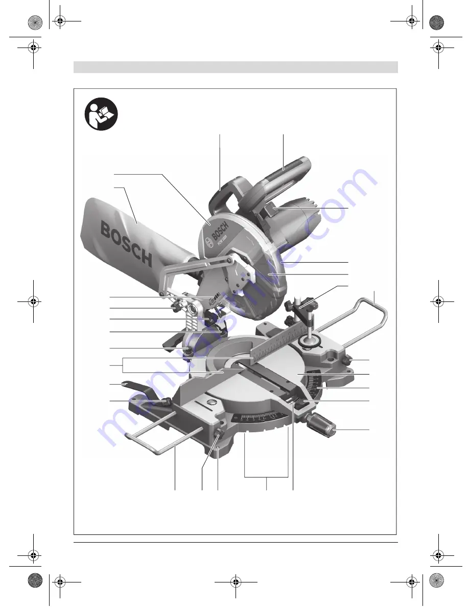
PCM 1800
15
14
3
6
1
8
19
20
21
22
23
17
18
4
891011
12
5
7
24
OBJ_BUCH-1142-001.book Page 2 Monday, January 25, 2010 8:52 AM
Страница 1: ...sch GmbH Power Tools Division 70745 Leinfelden Echterdingen Germany www bosch pt com 1 609 929 W25 2010 01 PS 23 XXX PCM 1800 en Original instructions OBJ_BUCH 1142 001 book Page 1 Monday January 25 2010 8 52 AM ...
Страница 2: ...1 609 929 W25 25 1 10 Bosch Power Tools 2 25 16 13 PCM 1800 15 14 3 6 2 1 8 19 20 21 22 23 17 18 4 8 9 10 11 12 5 7 7 24 OBJ_BUCH 1142 001 book Page 2 Monday January 25 2010 8 52 AM ...
Страница 3: ... 3 Bosch Power Tools 1 609 929 W25 25 1 10 27 29 32 27 2 26 33 34 2 30 28 31 OBJ_BUCH 1142 001 book Page 3 Monday January 25 2010 8 52 AM ...
Страница 4: ...1 609 929 W25 25 1 10 Bosch Power Tools 4 A B C1 C2 D 7 12 15 15 24 28 11 7 8 15 8 32 OBJ_BUCH 1142 001 book Page 4 Monday January 25 2010 8 52 AM ...
Страница 5: ... 5 Bosch Power Tools 1 609 929 W25 25 1 10 E1 E2 E3 F G H 39 22 17 37 3 4 36 5 40 41 18 26 6 38 35 11 13 12 14 OBJ_BUCH 1142 001 book Page 5 Monday January 25 2010 8 52 AM ...
Страница 6: ...1 609 929 W25 25 1 10 Bosch Power Tools 6 I J K L 21 34 19 42 29 20 3 OBJ_BUCH 1142 001 book Page 6 Monday January 25 2010 8 52 AM ...
Страница 7: ... 7 Bosch Power Tools 1 609 929 W25 25 1 10 M N O1 O2 P1 P2 10 13 44 20 19 43 33 29 29 42 42 45 45 46 OBJ_BUCH 1142 001 book Page 7 Monday January 25 2010 8 52 AM ...
Страница 8: ...1 609 929 W25 25 1 10 Bosch Power Tools 8 Q1 Q2 R S 3 2 30 18 30 47 1 47 OBJ_BUCH 1142 001 book Page 8 Monday January 25 2010 8 52 AM ...
Страница 9: ... cords increase the risk of electric shock e When operating a power tool outdoors use an extension cord suitable for out door use Use of a cord suitable for out door use reduces the risk of electric shock f If operating a power tool in a damp loca tion is unavoidable use a residual cur rent device RCD protected supply Use of an RCD reduces the risk of electric shock 3 Personal safety a Stay alert ...
Страница 10: ...h sharp cutting edges are less likely to bind and are easier to control g Use the power tool accessories and tool bits etc in accordance with these in structions taking into account the work ing conditions and the work to be per formed Use of the power tool for operations different from those intended could result in a hazardous situation 5 Service a Have your power tool serviced by a qual ified r...
Страница 11: ...te the machine without the in sert plate Replace a defective insert plate Without flawless insert plates injuries are possible from the saw blade f Check the cable regularly and have a dam aged cable repaired only through an author ised customer service agent for Bosch pow er tools Replace damaged extension cables This will ensure that the safety of the power tool is maintained f Store the machine...
Страница 12: ...tors Exposure to noise can cause hearing loss f Do not direct the laser beam at persons or animals and do not stare into the laser beam yourself not even from a distance This power tool produces laser class 2 laser radiation according to IEC EN 60825 1 This can lead to persons being blinded Observe the dimensions of the saw blade The hole diameter must match the tool spindle without play Do not us...
Страница 13: ...e angles horizontal 13 Angle indicator horizontal 14 Detents for standard mitre angles 15 Mounting holes 16 Fastening screw for ring spanner 17 Ring spanner 13 mm 18 Fence 19 Stop screw for 45 bevel angle vertical 20 Stop screw for 0 bevel angle vertical 21 Laser unit 22 Transport safety lock 23 Laser warning label 24 Dust bag 25 Blade guard 26 On Off switch 27 Drill holes for material clamp 28 Sa...
Страница 14: ...ation Damaged protective devices and parts must be immediately replaced by an authorised service centre Additionally required tools not in delivery scope Phillips screwdriver Angle gauge Open end spanner 13 mm Allen key 6 mm Chop and Mitre Saw PCM 1800 Article number 3 603 L01 040 Rated power input W 1800 Rated voltage V 240 Frequency Hz 50 No load speed min 1 4500 Cutting capacity max mm 70 Laser...
Страница 15: ...nerals and metal can be harmful to one s health Touching or breathing in the dusts can cause allergic reac tions and or lead to respiratory infections of the user or bystanders Certain dusts such as oak or beech dust are considered as carcinogenic especially in con nection with wood treatment additives chro mate wood preservative Materials containing asbestos may only be worked by specialists Use ...
Страница 16: ... If required clean all parts to be mounted prior to assembly Place the new saw blade onto the interior clamping flange 39 f When mounting the saw blade pay atten tion that the cutting direction of the teeth arrow direction on the saw blade corre sponds with the direction of the arrow on the blade guard Mount the clamping flange 38 and hexagon bolt 37 Press the spindle lock 36 until it engages and ...
Страница 17: ...ust be felt to engage in the detent Adjusting Any Horizontal Mitre Angle The horizontal mitre angle can be set in the range from 45 left side to 45 right side Loosen the locking knob 12 in case it is tight ened Press lever 11 turn saw table 9 via the lock ing knob left or right and adjust the desired mitre angle with help of the angle indicator 13 Tighten the locking knob 12 again Adjusting Vertic...
Страница 18: ...tand aside of the saw blade This protects your body against possible kickback Keep hands fingers and arms away from the rotating saw blade Do not cross your arms when operating the tool arm Permissible Workpiece Dimensions Maximal workpiece sizes Minimal workpiece sizes all workpieces that can be clamped left or right from the saw blade with the supplied ma terial clamp 6 130 x 35 mm x 5 mm length...
Страница 19: ...engage in the detent Checking The centre line of the angle indicator 13 must be in line with the 0 mark of the scale 10 Adjusting Remove the insert plate 33 Loosen the screw 44 using a commercial Phillips screwdriver and align the centre line of the angle indicator alongside the 0 mark Retighten the screw again Setting the Standard Bevel Angle 0 Vertical Bring the machine into the transport posi t...
Страница 20: ... length Adjusting see figure Q2 Loosen all Allen screws 31 with an Allen key 6 mm Turn the fence 18 until the angle gauge is flush over the complete length Retighten the screws again Checking the Laser Beam Position see figure R Draw a straight cutting line on the work piece Push the locking lever 3 and guide the tool arm slowly downward with the tool handle 2 Align the workpiece in such a manner ...
Страница 21: ...brush Clean the laser unit regularly 21 Disposal The machine accessories and packaging should be sorted for environmental friendly recycling The plastic components are labelled for catego rized recycling After sales Service and Customer Assistance Our after sales service responds to your ques tions concerning maintenance and repair of your product as well as spare parts Exploded views and informat...
Страница 22: ...1 609 929 W25 25 1 10 Bosch Power Tools 22 OBJ_BUCH 1142 001 book Page 22 Monday January 25 2010 8 52 AM ...