
LTC 7950, 7960 Series |
Instruction Manual
|
Installation
EN
| 8
Bosch Security Systems | January 03, 2005
3.3.2 Heater
These cameras are equipped with thermostatically and
electronically controlled electrical heating elements.
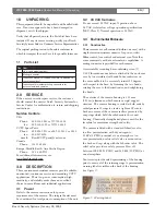
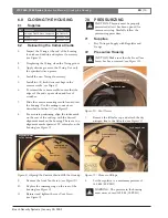
3.3.3 Humidity Indicator
The camera housing contains desiccant material and a
humidity indicator, visible from the front of the
camera through the glass window (see
Figure 2
). The
three areas, normally blue, turn pink as the internal
humidity increases. The indicator provides an extra
measure of reliability for the camera, and indicates
whether service is required.
Figure 2: Humidity Indicator
4.0
INSTALLATION
These units contain a high performance camera,
prepackaged in an environment-resistant, sealed
housing, pressurized with dry nitrogen. The cameras
are automated to a high degree, and factory-adjusted
for optimal performance. In normal conditions, no
initial or early life adjustments should be necessary.
The units provide reliable, unattended, continuous
performance in a wide variety of applications.
4.1
Cable Routing
CAUTION: Be sure cable wires do not pinch
or rub when connected to pan/tilt units.
Frayed, pinched, or broken wires can cause
fire, shock hazards, or system failure.
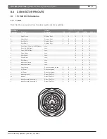
4.2
External Synchronization
See
Connector Pinouts
and the camera instructions for
external synchronization capabilities.
4.3
Phasing
The phase lock loop circuit controlling the sync
generator synchronizes the camera to the power line
zero crossing. This feature improves vertical interval
switching and time lapse recording. To obtain full
benefit of this feature, all cameras must be generated
on the same phase power. In low voltage (Class 2)
systems where the 24 VAC wires may easily be
reversed, color coding is recommended to maintain
correct power line phasing.
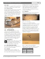
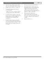
4.4
Mounting
Mount the camera using two or more of the seven (7)
1/4-20 threaded holes in the base (see
Figure 3
).
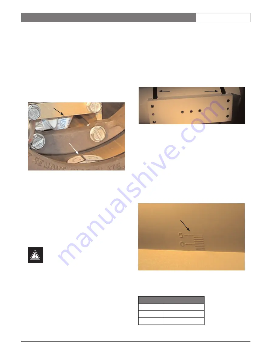
Figure 3: Mounting Holes
The support system should give adequate
consideration to the camera weight involved, as well as
any additional loading from snow, ice, and wind. The
cylindrical housing may be rotated with respect to
the base, by loosening the two stainless steel bands,
rotating the housing, and retightening the bands
(see
Figure 3
). This rotates the camera and the resulting
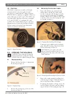
picture. Either set of index marks on the side of the
housing can be used to position the housing with the
camera base (see
Figure 4
).
Figure 4: Alignment of Housing With Base
If the camera is located in direct sunlight, an accessory
sunshield should be attached (ordered separately).
Humidity
Indicator
Index Marks on
Side of Housing
Desiccant Bag
Stainless Steel Bands
Camera Base
Sunshield Part Numbers:
Sunshield
Lens
TC1366-21
Fixed & 10X zoom models
TC1366
20X zoom models


