background image

LS1 Pendant Sphere Loudspeaker

Troubleshooting | en

13

Bosch Security Systems B.V.

Installation note

2018.06 | V.01 | F.01U.354.322

6

Troubleshooting

Problem

Possible Causes

Action

No Sound

Amplifier

Connect a known working test speaker to the amplifier outputs. If
there is no sound, check all electronics are on, the signal routing is
correct, the source is active; the volume is turned up, and so on.
Correct/Repair/Replace as necessary. If there is sound, the problem is
in the wiring.

Wiring

Verify you have connected the correct wire pairs to the amplifier. Play
something at low level through the amplifier (for example, from a CD
player or tuner). Connect the test speaker in parallel with the
malfunctioning line. If the sound has gone or is very weak, the line has
a short in it (possibly a severe scrape, pinch, or staple puncture). If
the sound level is normal the wire is open (possibly a cut wire or
missed connection). Using the test speaker, move down the line and
test each connection/junction until you find the problem and correct
it. Observe proper polarity.

Verify you have the inputs and outputs connected to the correct wires.
If the subwoofer input panel is not correctly wired, there will be little
or no sound. Observe proper polarity.

Poor Low-
Frequency
Response

Speakers Wired Out-
of-Polarity

When two speakers are connected out of polarity (out of phase), the
low frequencies will cancel each other acoustically. Carefully observe
the wire markings or tracers on your speaker wires. Verify the
amplifier (+) terminal is connected to the desired color-coded
transformer terminals and the amplifier (-) terminal is connected to
the red speaker terminals.

Intermittent
Output such as,
Crackling or
Distortion

Faulty Connection

Check all connections at amplifier and speakers to ensure they are
clean and tight. If the problem persists, it may be in the amplifier or
wiring. See other actions above.

Constant Noise
such as Buzzing,
Hissing, Humming

Defective Amplifier
or other Electronic
Device

If the noise is present but no program material is playing, the likely
cause is the signal chain in the electronics. Evaluate each component
as necessary to isolate the problem.

Poor System
Grounding or
Ground Loop

Check and correct the system grounding, as required.

If these suggestions do not solve your problem, contact your nearest dealer or distributor.

See also

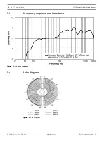
Polar diagram, page 16

Содержание LS1-UC10U

Страница 1: ...LS1 Pendant Sphere Loudspeaker LS1 UC10U en Installation note ...

Страница 2: ......

Страница 3: ...ices 4 2 Introduction 6 3 System overview 7 3 1 Packing list 7 3 2 Product information 8 3 3 Pendant suspension cable 8 4 Wiring 10 4 1 Ceramic block connector 10 4 2 Transformer Taps 10 5 Installation 11 6 Troubleshooting 13 7 Technical data 14 7 1 Dimensions 15 7 2 Circuit diagram 15 7 3 Frequency response and impedance 16 7 4 Polar diagram 16 7 5 Coverage 17 ...

Страница 4: ...ting such as in a crane or pulley situation No movement The pendent suspension cable is to be used to suspend static loads only Do not use the cable to suspend moving objects or objects likely to be subject to movement No joining Do not splice together the pendent suspension cable with another cable or other joining device The pendent suspension cable as supplied is the maximum length available an...

Страница 5: ...s document may be reproduced or transmitted in any form by any means electronic mechanical photocopying recording or otherwise without the prior written permission of the publisher For information on getting permission for reprints and excerpts contact Bosch All content including specifications data and illustrations in this manual are subject to change without prior notice ...

Страница 6: ... for use in a wide variety of environments and spaces to provide background speech and music The LS1 UC10U pendant sphere loudspeaker includes an inline DC blocking capacitor for use with DC supervision enabled systems The maximum allowed supervised voltage is 24 VDC The LS1 UC10U pendant sphere loudspeaker is UL1480 6 UL1408A CSA C22 1 and CSA C22 2 certified for fire and evacuation use Read thro...

Страница 7: ...note 2018 06 V 01 F 01U 354 322 3 System overview 3 1 Packing list The major components include in one box for the LS1 UC10U pendant sphere loudspeaker Item Quantity Description A 2 Pendant speakers B 2 Pendant suspension cables C 2 Ceramic Terminal Block D 1 Installation manual A x2 D C B x2 ...

Страница 8: ...ger bracket hole 3 3 Pendant suspension cable The pendant suspension cable is supplied with the LS1 UC10U kit The material is strong steel wire rope It is designed with a locking spring mechanism which secures the wire rope and allows for easy adjustment of the installation height up to 15 ft 4 57 m Working Load Limit The pendant suspension cable s WLL is based on the suspension being hung vertica...

Страница 9: ...er System overview en 9 Bosch Security Systems B V Installation note 2018 06 V 01 F 01U 354 322 LOAD 5 0 kg 5 0 kg 7 1 kg 7 1 kg 8 7 kg 8 7 kg 9 7 kg 9 7 kg 10 kg 45 30 60 15 15 45 60 30 Figure 3 1 Pendant cable working load limit ...

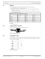
Страница 10: ...and Signaling Code NFPA72 Maximum recommended wiring length 0 5 dB loss 100 Watt 40 Watt 10 Watt 18 AWG 230 ft 560 ft 2300 ft 16 AWG 360 ft 900 ft 3600 ft 14 AWG 560 ft 1400 ft 5600 ft 12 AWG 910 ft 2300 ft 9100 ft See also Installation page 11 4 1 Ceramic block connector Connect the speaker using the ceramic block connector 0 From Amplifier To Speaker Figure 4 1 Ceramic block connector 4 2 Transf...

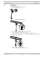
Страница 11: ...he pendant suspension cable length 3 Place the pendant suspension cable over the ceiling support 4 Thread the cable into the opposite side of the coupler 5 Once the proper height adjustment has been made put the cable tail through the through hole of the coupler and leave at least 10 cm 4 in of length The maximum audio wire length is 3 m 10 ft 6 Tighten the screw to secure the cable 7 Pinch the tw...

Страница 12: ... snap the support hanger through both main hanger bracket holes located on each individual hanger bracket leg 9 Attach a secondary auxiliary support cable onto of the secondary auxiliary support hole located on one bracket hanger leg 10 Secure the secondary auxiliary support cable to a different ceiling support point of the building structure ...

Страница 13: ...and outputs connected to the correct wires If the subwoofer input panel is not correctly wired there will be little or no sound Observe proper polarity Poor Low Frequency Response Speakers Wired Out of Polarity When two speakers are connected out of polarity out of phase the low frequencies will cancel each other acoustically Carefully observe the wire markings or tracers on your speaker wires Ver...

Страница 14: ... terminal Enclosure ABS fire rated Color White RAL 9010 Dimensions H x Dia 254x185 mm 10x7 3 in Net weight 3 kg 6 6 lb 4 Shipping weight 9 kg 19 8 lb Support hardware Two 2 pendant suspension cables Operating temperature 25 C to 55 C 13 F to 131 F Storage and transport temperature 40 C to 70 C 40 F to 158 F Relative humidity 95 Approvals UL1480 6 UL1480A CSA C22 2 CSA 22 1 CE 1 Full space measurem...

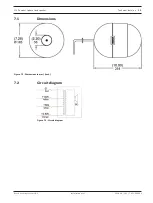
Страница 15: ...ant Sphere Loudspeaker Technical data en 15 Bosch Security Systems B V Installation note 2018 06 V 01 F 01U 354 322 7 1 Dimensions Figure 7 1 Dimensions in mm inch 7 2 Circuit diagram Figure 7 2 Circuit diagram ...

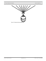
Страница 16: ...data LS1 Pendant Sphere Loudspeaker 2018 06 V 01 F 01U 354 322 Installation note Bosch Security Systems B V 7 3 Frequency response and impedance Figure 7 3 Frequency response 7 4 Polar diagram Figure 7 4 Polar diagram ...

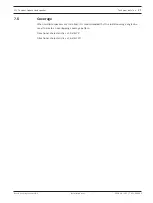
Страница 17: ... B V Installation note 2018 06 V 01 F 01U 354 322 7 5 Coverage When multiple speakers are installed it is recommended that the 6 dB coverage angles be used to create an overlapping coverage pattern Directional characteristics at 3 dB 75 Directional characteristics at 6 dB 120 ...

Страница 18: ......
Страница 19: ...Bosch Security Systems B V Torenallee 49 5617 BA Eindhoven Netherlands www boschsecurity com Bosch Security Systems B V 2018 ...

Отзывы: