background image

28

en | wLSN Devices

wLSN

F01U138553 | 01 | 2010.05

System Reference Guide

Bosch Security Systems, Inc.

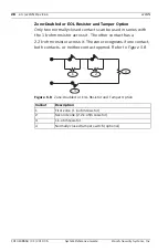
Zone-Doubled or EOL Resistor and Tamper Option

Only two normally-closed contacts can be used in series with 

the 1 k-ohm resistor across it. The other contact has a 

2.2 k-ohm resistor across it. The zone recognizes if one contact, 

both contacts, or neither contact opened. Refer to 

Figure 5.8

.

Figure 5.8

Zone-Doubled or EOL Resistor and Tamper Option

Callout

Description

1

First zone (1 k-ohm resistor)

2

Second zone (2.2 k-ohm resistor)

3

1 k-ohm resistor

4

Normally-closed tamper switch (optional)

1

2

3

4

Содержание ISW-BDL1-W11PGX

Страница 1: ...wLSN wireless Local SecurityNetwork en System Reference Guide ...

Страница 2: ......

Страница 3: ... 2 Defaulting a wLSN Device 13 5 wLSN Devices 17 5 1 wLSN Installation Tool 17 5 2 wLSN Diversity Hub 19 5 3 wLSN PIR and Dual Motion Detectors 22 5 3 1 Sensitivity Settings 22 5 3 2 Walk Test 24 5 4 wLSN Door Window Contact 26 5 5 wLSN Recessed Door Window Contact 29 5 6 wLSN Mini Door Window Contact 30 5 7 wLSN Inertia Detector 31 5 7 1 Sensitivity Settings 32 5 7 2 Test Mode 33 5 8 wLSN Relay M...

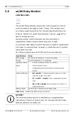
Страница 4: ...1 wLSN Key Fob 42 5 12 wLSN Smoke Detector 44 5 13 wLSN Glass Break Detector 49 5 13 1 Installation Considerations 51 5 13 2 Sensitivity Settings 51 5 13 3 Testing 53 5 13 4 Low Battery Indication 55 5 13 5 Entering RFSS Mode 55 6 Trademarks Icons and Symbols 56 6 1 Trademarks 56 6 2 Icons and Symbols 56 ...

Страница 5: ...ther with the control panel s documentation and each device s installation instructions to complete the installation process Table 1 1 wLSN Products and Instructions Product wLSN Device Manual Part Number ISW BIT1 HAX HBX HCX Installation Tool F01U008748 ISW BHB1 WX Hub F01U500915 ISW BPR1 W13PX PIR Motion Detector F01U500908 ISW BDL1 W11PGX PHX PKX Dual Motion Detector F01U500901 ISW BMC1 R135X R...

Страница 6: ...duce the radio frequency RF range of a wLSN device Avoid installing the devices where excessive humidity or moisture or temperatures outside of the acceptable operating range exist When installing a wLSN Network plan your installation based on the control panel and wLSN specifications and the radio frequency signal strength RFSS between remote devices and the wLSN Diversity Hub Table 2 1 wLSN Gene...

Страница 7: ...onsumer you are legally obliged to take batteries to a suitable collection point You can return used batteries free of charge to the point of sales or to a communal collection point Batteries can contain substances that are hazardous to the environment or health Only dispose of discharged batteries in the container provided and in the case of lithium batteries mask the poles Batteries are identifi...

Страница 8: ... testing for RF signal strength the wLSN Diversity Hub and the control panel must be set to the same EN50131 Security Grade CAUTION If you have wLSN devices that you will not immediately install reinsert the battery tabs or remove the batteries to prevent battery depletion NOTICE Do not permanently install the wLSN Diversity Hub or any wLSN devices until you receive acceptable or better signal str...

Страница 9: ...S Mode switch settings Refer to Figure 5 2 Page 20 for the location of the rotary switches Table 3 1 S1 Switch RFSS Mode Settings Refer to the individual device s specification for the EN50131 classification 4 Find a suitable location for the hub base and apply power by connecting it to the control panel refer to the control panel s installation instructions or by temporarily connecting a 9 VDC to...

Страница 10: ...ect Mode 3 to test RFSS 4 Press 3 to select Mode 3 Mode 3 determines the signal strength based on the signal to noise ratio SNR SNR is measured in decibels dB Unacceptable 30 dB Acceptable 35 dB Good 40 dB Very Good 45 dB Excellent 50 dB 5 Hold the wLSN Installation Tool at the installation location for at least 10 sec CAUTION When testing for RF signal strength the wLSN Diversity Hub and the cont...

Страница 11: ...llation Tool is is either unacceptable or marginal find a better location for the wireless device 7 Repeat Step 5 until all bases are mounted in acceptable locations Do not mount the wireless devices onto the bases at this time 8 Set the rotary switch on the wLSN Diversity Hub to normal operation Position 1 for Data Bus Address 50 default Position 2 for Data Bus Address 51 9 Configure the wLSN dev...

Страница 12: ...Diversity Hub identifies and includes new devices into a system For the wLSN network to operate properly the following process must occur For specific information on the discovery process refer to your control panel documentation To default a device that is already enrolled into an existing wLSN network refer to Section 4 2 Defaulting a wLSN Device page 13 Discover Devices Establish Network Config...

Страница 13: ...efly turns off and then on indicating that the wLSN device was successfully defaulted Defaulting a Glass Break Detector or Siren ISW BSR1 WIX and WOX If the wall tamper tab is removed and you must default the Glass Break Detector Indoor Siren ISW BSR1 WIX or Outdoor Siren ISW BSR1 WOX 1 Remove or disconnect the batteries from the device 2 Place the device on a flat surface to depress the wall tamp...

Страница 14: ...ion of the RFSS Mode LED 5 Release the cover tamper switch within five sec after the RFSS Mode LED turns on The device is now defaulted Figure 4 1 wLSN Glass Break Tamper Switches and RFSS Mode LED Figure 4 2 ISW BSR1 WIX WOX Tamper Switches and RFSS Mode LED Callout Description 1 Wall tamper switch back of detector 2 RFSS LED inside of detector 3 Cover tamper switch inside of detector 3 1 1 2 O N...

Страница 15: ...r from Base 2 Remove the batteries 3 Separate the housing cover and base by inserting a flat head screwdriver between the cover and base Figure 4 4 Separate Housing Cover and Base 4 Turn the housing base over and locate the transmitter printed circuit board PCB 5 Remove the jumper from the transmitter PCB and reinsert it over both pins Callout Description 1 Wall tamper switch back of siren 2 Cover...

Страница 16: ...d replace it over one pin normal operating position 8 Replace the housing cover on the housing base Align the sounder with the notch on the housing cover and push firmly until the cover and base snap into place 9 Close the battery case and mount the detector onto its mounting base Callout Description 1 Housing base 2 Transmitter PCB 3 Jumper plug in normal operating position plug covers a single p...

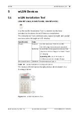
Страница 17: ...th and packet success ratios through an LCD display Table 5 1 wLSN Installation Tool Specifications The status LED indicates charging status when placed in a docking station Figure 5 1 wLSN Installation Tool Specification Value Power Docked 12 VDC nominal 7 VDC to 14 VDC 12 VDC plug in power pack supplied Batteries 3 AAA NiMH rechargeable batteries that require an initial charge of at least 7 hour...

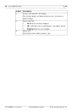
Страница 18: ...scription 1 2 line x 16 character LCD display The display flashes and beeps every four sec to indicate a status change 2 Power Indicator On Batteries are fully charged Off Installation tool is operating on only battery power Flashing Batteries are charging 3 Status LED LED flashes when battery power is low ...

Страница 19: ...wLSN Diversity Hub provide spatial diversity for improved RF signal quality in transmit and receive modes An LED on the front provides device status Table 5 2 wLSN Diversity Hub Specifications Specification Value Wire Gauge 0 14 24 AWG to 1 5 mm 18 AWG Power 12 VDC nominal 7 to 14 VDC Wire Length 300 m 1000 ft Current Draw Maximum 60 mA Wall and Cover Tamper Switch Transmits a tamper signal when t...

Страница 20: ... is in RFSS Mode S2 and S3 are reserved for future use Refer to Figure 5 2 for switch location and Table 5 3 for switch settings Figure 5 2 wLSN Diversity Hub Rotary Switch Table 5 3 S1 Settings Switch Position Operation 1 Default Data Bus Address 50 2 Data Bus Address 51 4 RFSS Mode Antenna 1 full power 5 RFSS Mode Antenna 1 Grade 2 6 dB attenuation 6 RFSS Mode Antenna 2 full power 7 RFSS Mode An...

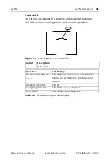
Страница 21: ... and normal operation Figure 5 3 wLSN Diversity Hub Status LED Table 5 4 wLSN Diversity Hub LED Displays Callout Description 1 Status LED Operation LED Display Self Test and Hardware Failure LED flashes twice each sec This indicates failure The wLSN Diversity Hub does not operate Standard Operation LED on Configuring Network LED flashes once every 2 sec RFSS Mode LED flashes once every 4 sec 1 ...

Страница 22: ...wLSN PIR and Dual Motion Detector Specifications 5 3 1 Sensitivity Settings Sensitivity settings are set at the control panel Refer to the control panel s documentation for detailed information Standard Sensitivity default setting Use this setting when pets are present in the area to be monitored Standard sensitivity provides excellent detection performance and is the least sensitive to false alar...

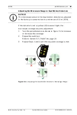
Страница 23: ...age requires adjustment 1 Turn the potentiometer as shown in Figure 5 4 to increase or decrease the coverage 2 Repeat the walk test Refer to Section 5 3 2 Walk Test page 24 3 Repeat Steps 1 and 2 until the required coverage is met Figure 5 4 Adjusting the Dual Motion Detector s Microwage Range NOTICE The microwave sensor in the dual motion detectors is adjusted in the factory to sense motion to a ...

Страница 24: ...its a signal to the control panel and restarts a 90 sec timer If no motion occurs within 90 sec the red LED flashes for the last 10 sec to indicate that the Walk Test mode is ending Detected motion restarts the 90 sec timer 1 Start at the pattern s expected boundary and walk across the pattern moving closer to the detector at each pass while observing the LED Refer to Figure 5 5 Refer to Table 5 6...

Страница 25: ...trol panel enter the appropriate command sequence at the control panel to exit from the Walk Test mode At the detector the detector returns to normal operation after 90 sec of inactivity LED Color Function Green to red fast flash Power up Walk Test disabled Green lights for 3 sec Motion detected by PIR Yellow lights for 3 sec Motion detected by microwave To adjust the detector s microwave range re...

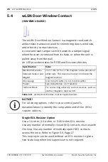
Страница 26: ...m or 3 65 k ohm EOL resistor Use any number of normally closed NC contacts in series with the loop Use any number of normally open NO contacts across the loop Refer to Figure 5 6 Page 27 This loop style can be used without an EOL resistor to give a two state loop when line supervision is not required Specification Value Maximum Distance between Sensor and Magnet 12 7 mm 0 5 in The magnet can be pl...

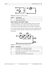
Страница 27: ...m resistor across it Refer to Figure 5 7 Do not use contacts across the loop The zone recognizes that one or more of the contacts is opened but not which ones or how many Figure 5 7 Alarm Resistor and Tamper Option Callout Description 1 Normally open NO 2 Normally closed NC Callout Description 1 1 5 k ohm or 2 2 k ohm alarm resistor 2 1 5 k ohm or 2 2 k ohm alarm resistor Optional up to four addit...

Страница 28: ...ies with the 1 k ohm resistor across it The other contact has a 2 2 k ohm resistor across it The zone recognizes if one contact both contacts or neither contact opened Refer to Figure 5 8 Figure 5 8 Zone Doubled or EOL Resistor and Tamper Option Callout Description 1 First zone 1 k ohm resistor 2 Second zone 2 2 k ohm resistor 3 1 k ohm resistor 4 Normally closed tamper switch optional 1 2 3 4 ...

Страница 29: ...able 5 9 wLSN Recessed Door Window Contact Specifications Figure 5 9 wLSN Recessed Door Window Contact Specification Value Power One CR2 lithium battery 3 VDC Maximum Distance between Reed Switch and Magnet 12 7 mm 1 2 in Required Drill Tools 19 mm 3 4 in drill bit and 22 mm 7 8 in spade bit Circuit Board Removal Needle nose pliers are recommended NOTICE Mounting the wLSN Recessed Door Window Cont...

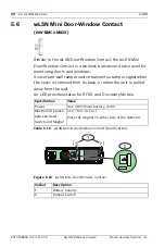
Страница 30: ...ll tamper switch transmits a tamper signal when the cover is removed from its base or when the unit is pulled away from the wall An LED provides status for RFSS and Discovery Modes Table 5 10 wLSN Mini Door Window Contact Specifications Figure 5 10 wLSN Mini Door Window Contact Specification Value Power One CR2 lithium battery 3 VDC Maximum Distance between Reed Switch and Magnet 12 7 mm 0 5 in Pl...

Страница 31: ... cover is removed from its base or when the unit is pulled away from the wall An LED provides status for Test RFSS and Discovery Modes Table 5 11 wLSN Inertia Detector Specifications Specification Value Maximum Distance between Detector and Magnet 12 7 mm 1 2 in Place the magnet on either side of the detector Power 2 AA batteries 1 5 V alkaline NOTICE Sensor element orientation is critical to the ...

Страница 32: ...el refer to your control panel s documentation for more information The sensor element has two types of detection Gross Attack Minor Attack Gross Attack is always enabled Minor Attack is very sensitive and can be disabled Callout Description 1 Remove the sensor element 2 Turn the sensor element as needed 3 Ensure that the arrow on the sensor element points up 1 2 3 90 NOTICE Route the wiring from ...

Страница 33: ...enabled Minor Attack has two settings Four taps Eight taps When a tap occurs a 90 sec timer starts If the tap count exceeds the four or eight count threshold within 90 sec the sensor transmits an alarm signal 5 7 2 Test Mode The unit is automatically in Test mode for the first 10 minutes after power up The green LED flashes One time to indicate that initialization is complete and the unit is in Te...

Страница 34: ...moved from its base or when the unit is pulled away from the wall An LED provides status for RFSS and Discovery Modes Table 5 12 wLSN Relay Module Specifications Specification Value Wire Gauge 0 14 mm 22 AWG to 1 5 mm 14 AWG Power Four AA batteries 1 5 V alkaline Auxiliary Power Input 12 VDC nominal 6 VDC to 14 VDC 50 mA current draw Compatible with any 12 VDC nominal power supply Terminal Blocks ...

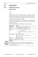
Страница 35: ...ver is removed from its base or when the unit is pulled away from the wall An LED provides status for RFSS and Discovery Modes Table 5 13 ISW BSR1 WX Specifications Specification Value Wire Gauge 0 14 mm 22 AWG to 1 5 mm 14 AWG Power Four AA batteries 1 5 V alkaline Auxiliary Power Input 12 VDC nominal 6 VDC to 14 VDC 50 mA current draw Compatible with any 12 VDC nominal power supply Terminal Bloc...

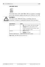
Страница 36: ... 1 m 3 ft Table 5 14 ISW BSR1 WIX Specifications WARNING The siren is loud When the siren is sounding wear ear protection or remain a reasonable distance from the device Specification Value Battery Pack Life Up to 3 years with normal usage Voltage Battery pack contains two lithium thionyl chloride batteries each rated at 3 6 VDC 13 Ah Current Alarm 500 mA Standby 0 05 mA Acoustic Sound Level 90 dB...

Страница 37: ... Siren Specifications WARNING The siren is loud and the LED array is bright When the siren is sounding wear ear protection or remain a reasonable distance from the device When the LED is on do not look directly at it Specification Value Battery Pack Life Up to 3 years with normal usage Voltage Battery pack contains two lithium thionyl chloride batteries each rated at 3 6 VDC 13 Ah Current Alarm Si...

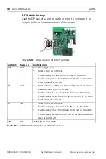
Страница 38: ... 90 sec Flashes every 1 5 sec from 0 90 sec of the alarm Flashes every 3 sec from 90 sec to 30 min of the alarm Flash stops after 30 min ON OFF Siren activates for 60 sec followed by 30 sec of silence then activates again for 60 sec Flashes every 1 5 sec from 0 to 150 sec of the alarm Flashes every 3 sec from 150 sec to 30 min of the alarm Flash stops after 30 min ON ON Siren is limited to 90 sec ...

Страница 39: ...ature at the transceiver module housing not at the water probe goes below 7 C 45 F for more than 30 sec the sensor transmits a signal to the wLSN Diversity Hub 5 10 1 Installation Considerations The wLSN Water Sensor Low temperature Sensor is not intended to monitor water levels in storage tanks or other liquids be permanently submerged in water or detect the absence of water To ensure proper oper...

Страница 40: ...sor and low temperature sensor functions test them as described in the following sections Testing and Enabling When Both Sensors are Required 1 During the Point Test test the low temperature sensor first Refer to Table 5 17 for instructions The system announces Point xx was tested 2 Test the water sensor Refer to Table 5 17 for instructions Testing and Enabling When Only the Water Sensor is Requir...

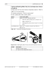
Страница 41: ...ed Do not connect the water sensor probe Table 5 17 Testing and Enabling Procedures Figure 5 14 Enabling the Water Probe and Low Temperature Functions Sensor To test and enable Water Select one of the following methods Short the water probe pins for at least 5 sec Refer to Figure 5 14 Submerge the water probe in water for at least 5 sec Low temperature Short the T pads for at least 5 sec Refer to ...

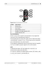
Страница 42: ...eatures include Five buttons Two buttons for arming and disarming the system Two programmable buttons for controlling lights garage doors and so on To operate the intended output press and hold the appropriate button for at least one sec One button for operating the high intensity LED Two LEDs Status LED High intensity LED suitable for use as a flashlight Specification Value Power Two CR2032 lithi...

Страница 43: ...sec This indicates that commands were transmitted to the control panel Pressing and holding both the arm and disarm buttons together for 1 sec transmits a panic signal to the control panel LED A flashing red status LED during key fob inactivity is an indication to replace the batteries For specific information regarding the various LED states refer to your control panel s documentation Callout Des...

Страница 44: ... 46 and Table 5 21 Page 46 A self diagnostic feature monitors detector sensitivity and operational status A cover tamper switch transmits a tamper signal when the cover is removed from its base The optical chamber is removable for easy maintenance The detector complies with EN14604 Table 5 19 wLSN Smoke Detector Specifications Figure 5 16 wLSN Smoke Detector Overview Specification Value Power Two ...

Страница 45: ... detector automatically resets when smoke is no longer present A detector that fails to activate with the smoke test might require cleaning or replacement Sensitivity Test The detector includes a Sensitivity Level Test mode for determining the detector s sensitivity 1 Press and hold the Test Silence button for 4 sec The LED flashes 1 to 9 times Refer to Figure 5 16 Page 44 2 Count the number of LE...

Страница 46: ...Action 1 Self diagnostics failure Return the device for service or replacement 2 to 3 The device is becoming insensitive Clean the detector and retest If the error continues replace the detector 4 to 7 The detector is within the normal sensitivity range 8 to 9 The device is becoming too sensitive Confirm that the smoke chamber is snapped down securely Clean the sensor and retest LED Status Flashin...

Страница 47: ...nterior annually or as needed To clean the detector 1 Rotate the detector counter clockwise to remove it from the mounting base 2 Remove the batteries 3 Slide a flat head screwdriver into the slot on the detector cap and gently push down to pry the cap off Refer to Figure 5 17 Page 47 Figure 5 17 Remove the Detector Cap 4 Squeeze the optical chamber where indicated and pull it up and away from the...

Страница 48: ...p align the cap with the detector press the cap onto the detector and turn the cap clockwise to snap it firmly into place 8 Observing the proper polarity install the batteries and the battery cover If the batteries are not installed the detector does not fit properly onto the mounting base 9 Mount the detector onto the mounting base 10 Test the detector s sensitivity Refer to Section Sensitivity T...

Страница 49: ...s Break Detector Specifications Table 5 23 wLSN Glass Break Detector Acoustic Capabilities Specification Value Power 2 AA batteries 1 5 V alkaline Minimum pane size for all types of glass 28 cm x 28 cm 11 in x 11 in Refer to Table 5 23 for glass types and thicknesses Laminated 0 32 cm to 1 43 cm 0 1 in to 0 6 in Range Minimum No minimum range Maximum 7 6 m 25 ft Glass Type Glass Thickness Plate 0 ...

Страница 50: ...LSN Glass Break Detector Layout Callout Description 1 Cover tamper switch 2 AA batteries 3 Service door 4 Test Mode pads 5 Sensitivity DIP switches 6 EVENT LED green 7 ALARM LED red 8 LED ENABLE switch off position 9 Housing screw 10 RFSS Mode LED remove housing screw and cover piece EVENT 1 2 3 4 5 6 7 8 9 10 ...

Страница 51: ... same wall as the protected glass on free standing posts or pillars in rooms with noisy equipment such as air compressors bells and power tools 5 13 2 Sensitivity Settings 1 If the front housing is attached carefully open the service door Item 3 Figure 5 19 Page 50 2 Enable the EVENT and ALARM LEDs for test purposes by sliding the LED ENABLE switch Item 8 Figure 5 19 Page 50 in the direction of th...

Страница 52: ...reen EVENT LED Item 6 Figure 5 19 Page 50 for approximately one min If the green LED flashes relocate the unit or adjust the sensitivity DIP switches to decrease the sensitivity 7 Repeat Steps 3 through 6 until you achieve the best sensitivity level 8 After setting the sensitivity slide the LED ENABLE switch Item 8 Figure 5 19 Page 50 to the OFF position Sensitivity SENS1 SENS2 Approximate Range M...

Страница 53: ...1 Carefully open the service door of the detector 2 Insert a screwdriver into the slot next to the sensitivity switches Item 1 Figure 5 20 Page 52 3 Touch both test pads at the same time with the tip of the screwdriver The EVENT LED green Item 6 Figure 5 19 Page 50 flashes once each second If the green LED does not flash repeat Steps 2 and 3 Callout Description 1 ACTIVATE TEST switch 2 Start butto...

Страница 54: ...gnals properly its red ALARM LED lights for 3 sec If the red ALARM LED does not light return to Section 3 RFSS Mode RF Signal Strength page 8 to reposition the detector Exiting from Test Mode To exit from the Test Mode locally 1 Carefully open the service door of the detector 2 Insert a screwdriver into the slot next to the sensitivity DIP switches Item 5 Figure 5 19 Page 50 3 Touch both test pads...

Страница 55: ...ndependent of each other and do not necessarily occur at the same time Receiving either condition indicates a low battery 5 13 5 Entering RFSS Mode To enter RFSS Mode if the wall tamper tab is removed 1 Take the detector to its planned mounting location 2 Remove and reinsert the batteries 3 Press and hold the wall tamper switch Refer to Figure 5 22 4 Quickly press and release the cover tamper swit...

Страница 56: ...ls Refer to Table 6 1 for descriptions of the icons and symbols used in the wLSN documentation Table 6 1 Icons and Symbols Icon Symbol Description Not Pet Friendly Pet Friendly appropriate weights below graphic Point away from rotating machines Point away from objects that rapidly change temperature Do not mount in sunlight Do not point toward window Do not mount outside Device has a wall or cover...

Страница 57: ......

Страница 58: ...Bosch Security Systems Inc 130 Perinton Parkway Fairport NY14450 USA www boschsecurity com Bosch Security Systems Inc 2010 ...

Отзывы: