EN
| 11
Bosch Security Systems | 12 August 2005
HSG9583 Series | Instruction Manual | HSG9583/22,/52,/53
5
HSG9583/22, HSG9583/52,
and HSG9583/53 MODELS
5.1
Camera/Lens Wiring
Installation for these models is in accordance with
SECTION 4, INSTALLATION, except as noted herein.
WARNING: For wiring cameras and lenses,
use only the cables specified in the
INSTALLATION, Cable Requirements chart.
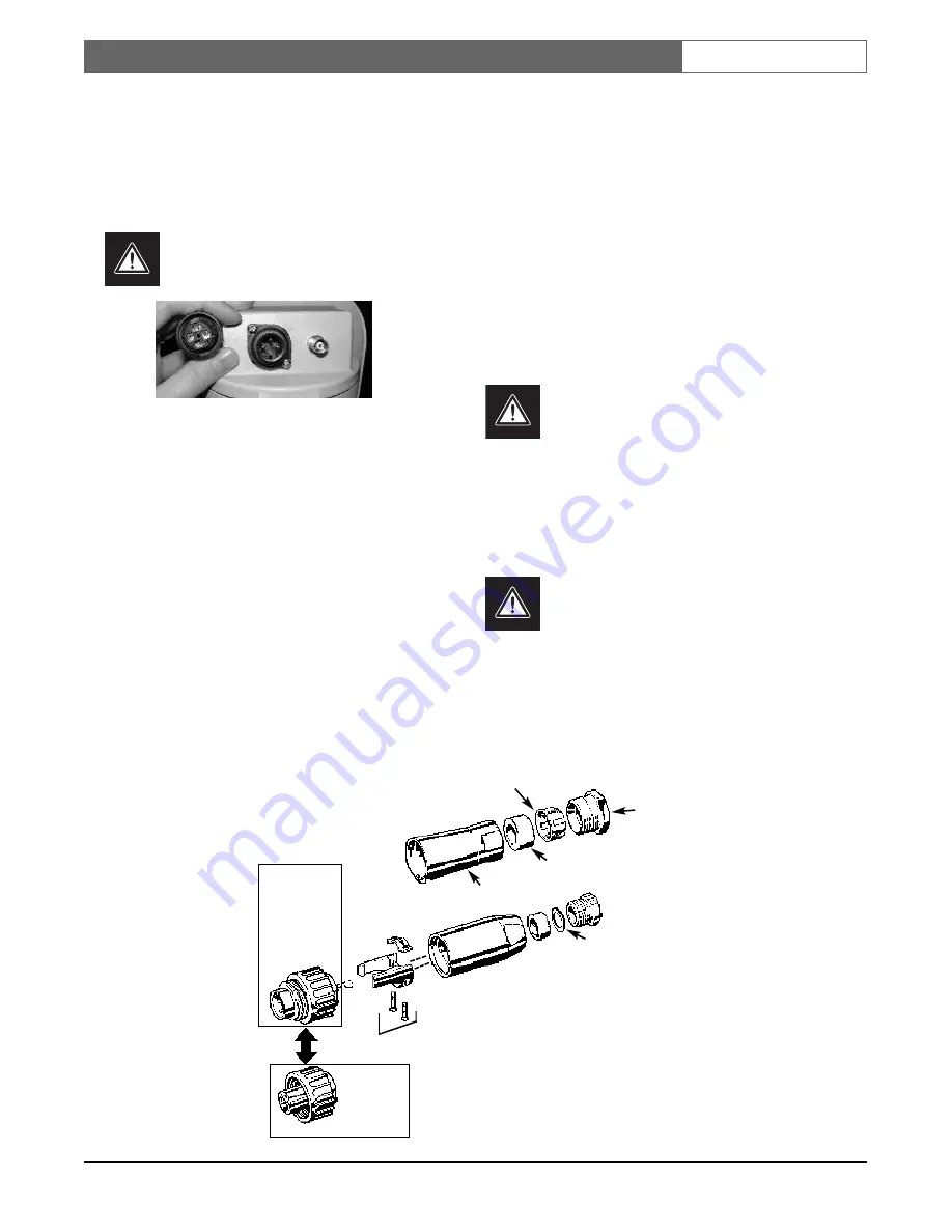
Figure 8: Electrical Connections
1.
All electrical power connections are made
through the 4-pin connector (see FIGURE 8).
2.
Cut the power cord on 230VAC camera
models, leaving enough cable for connection to
the terminal block. Strip no less than 6mm
(0.25in) and no more than 8mm (0.31in) of
insulation away from the wire. Be sure not to
nick the wires. Insert the power cord through
the back shell assembly and strain relief (see
FIGURE 9).
3.
The terminal block provided on these units
accepts wire ranging from 0,5 to 2,5mm
2
(20 to 14AWG). When using larger wire sizes,
splice to a smaller size wire at the terminal
block end.
4.
Connect the power input cable to the screw
terminals on the provided mating connector
(see FIGURE 9 and Wiring Diagram for pin
connections).
Table 2 - Wiring Diagram (4-Pin)
Pin
Function
Harness Wire Color
1
AC Neutral
Blue
2
AC Hot
Brown
3
No Connection
(Do not use)
4
Ground
Green/Yellow
WARNING: Use only 24VAC power for
HSG9583/22 Models. These models have
female connectors to prevent them from
being connected to the mating connector that
is provided with /52 and /53 Models that
require 230VAC. Ensure that 230VAC is not
applied to to the male mating connector.
5.2
Video Coax Connection
WARNING: For wiring of the video coax
connection, use only the cables specified in
the INSTALLATION, Cable Requirements
chart.
1.
A video connection is provided on the rear of
the housing. Connect video cable to the
housing using a BNC connector.
2.
An internal video connection is provided.
Connect the BNC cable to the camera.
Female
230VAC
ONLY!
24VAC
ONLY!
Coupling
Ring Male
Metal Washer
Back Shell
Cable Nut
Sealing
Gasket
Clamping
Ring
Internal
Strain
Relief
Figure 9: Mating Connector 4-Pin Assembly
Содержание HSG9583 Series
Страница 14: ...HSG9583 Series Instruction Manual EN 14 Bosch Security Systems 12 August 2005 ...
Страница 28: ...Série HSG9583 Manuel d utilisation FR 14 Bosch Security Systems 12 August 2005 ...
Страница 54: ...Serie HSG9583 Manual de instrucciones ES 14 Bosch Security Systems 12 August 2005 ...
Страница 91: ...Série HSG9583 Manual de Instrução PT 13 Bosch Security Systems 12 August 2005 ...


