English |
19
Preselecting the speed
You can preselect the required speed using the speed
preselection thumbwheel
(28)
, even during operation.
1−2
low speed
3−4
medium speed
5−6
high speed
The values shown in the table are guide values. The required
speed is dependent on the material and the work conditions
and can be determined by practical trials.
Material
Router bit dia-
meter [mm]
Thumbwheel
position
Hardwood (beech)
4–10
12–20
22–40
5–6
3–4
1–2
Softwood (pine)
4–10
12–20
22–40
5–6
3–6
1–3
Chipboard
4–10
12–20
22–40
3–6
2–4
1–3
Plastics
4–15
16–40
2–3
1–2
Aluminium
4–15
16–40
1–2
1
After working at a low speed for an extended period, you
should operate the power tool at the maximum speed for ap-
proximately three minutes without load to cool it down.
Switching on/off
Before switching on, set the required routing depth (see
"Setting the routing depth", page 19).
To
switch on
the power tool, press the on/off switch
(29)
and keep it pressed.
Press the lock-on button
(2)
to
lock
the on/off switch
(29)
in
this position.
To
switch off
the power tool, release the on/off switch
(29)
;
or, if the switch is locked with the lock-on button
(2)
, briefly
press the on/off switch
(29)
and then release it.
Constant electronic control
The Constant Electronic keeps the speed at no load and un-
der load virtually consistent, guaranteeing uniform perform-
ance.
Soft start
The electronic soft start limits the torque when the power
tool is switched on and increases the service life of the mo-
tor.
Overload protection
The overload protection prevents impermissibly high current
consumption in the event of extreme overload. This can lead
to a reduction in motor speed and power output or in ex-
treme cases to motor standstill.
Once the load has been removed from the power tool, the
motor immediately runs up or back to working speed.
Restarting Protection
The restart protection feature prevents the power tool from
uncontrolled starting after the power supply to it has been
interrupted.
To
restart
the tool, set the on/off switch
(29)
to the "off" po-
sition and then switch the power tool on again.
Release Lever (see figure C)
The release lever
(23)
is automatically reset when you let go
of it. For better retention force, the release lever
(23)
must
be pulled back as far as it will go. The retention force can be
readjusted if required. To do so, insert an hex key (4 mm)
into the opening on the handle. Turn the hex key clockwise
to increase the retention force, and turn it anticlockwise to
reduce the retention force.
Setting the routing depth
u
The routing depth must only be set while the power
tool is switched off.
For coarse adjustment of the routing depth (see figure
D
and
E
), proceed as follows:
– Place the power tool with a fitted router bit onto the work-
piece you want to machine.
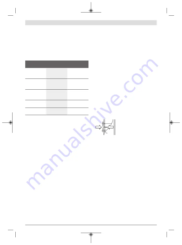
– Set the fine-adjustment path to the centre position with
the adjustment knob
(25)
. To do this, turn the knob
(25)
until the markings
(19)
match those shown in the figure.
Then turn the scale
(24)
to
0
.
(19)
– Set the step buffer
(9)
to
the lowest step; the step
buffer audibly clicks into
place.
– Loosen the screw
(15)
on
the depth stop
(14)
so
that the depth stop
(14)
is freely movable.
– Push the release lever
(23)
back and slowly guide the
router down until the router bit
(5)
touches the work-
piece surface. Let go of the release lever
(23)
again to
lock this position.
– Press the depth stop
(14)
down until it is resting on the
step buffer
(9)
.
GOF 1250 LCE:
Switch on the digital depth display at the
on/off switch
(18)
. Press the button
(16)
for setting the
zero point of the depth stop
(14)
.
GOF 1250 CE:
Set the slide with the index mark
(27)
to
position
0
on the routing depth scale
(26)
.
– Set the depth stop
(14)
to the required routing depth and
tighten the screw
(15)
on the depth stop
(14)
.
GOF 1250 CE:
Make sure you do not adjust the slide with
the index mark
(27)
any more.
– Push the release lever
(23)
and guide the router to the
uppermost position.
For larger routing depths, you should perform the cut in sev-
eral phases, so that only a small amount of material is re-
moved after each cut. You can use the step buffer
(9)
to di-
vide the routing process into several steps. To do this, set
the required routing depth with the smallest step of the step
buffer and, for the first cutting phases, select the higher
Bosch Power Tools
1 609 92A 57T | (03.02.2020)


