


Aspiration smoke detectors LSN improved
System overview | en
19
Bosch Sicherheitssysteme GmbH
Quick installation guide
2020.04 | 5 | F.01U.029.274
1
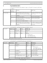
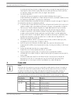
System overview
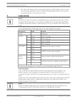
For the connections of the FAS-420-TP device, refer to graphic
01, page 4. For the connections
of the FAS-420-TT device, refer to graphic
Position in
figure
Function
Explanation
FAS-420 series
1
Cable bushing for connection of fire panel
and additional power supply (input/
output)
1 x M 20, for cable diameters of
8 - 12 mm
2
Pipe system 1 connection
For Ø 25 mm pipe system
3
Pipe system 2 connection (only for devices
with a two pipe system)
For Ø 25 mm pipe system
4
Connection for air-return pipe
5
Cable bushing for connection of fire panel
and additional power supply (input/
output)
2 x M 25 for cable diameters of
9 - 14 mm (expandable to 14 -
18 mm)
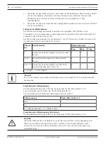
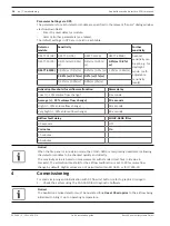
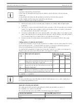
For FAS-420-TP1 and FAS-420-TP2 LEDs, refer to graphic
FAS-420-TP
Designation
LED
Color
Explanation
I
Operation
Green
Operation
II
Alarm
1
Red
Alarm
III
Fault
Yellow
Fault
–
in the pipe system
–
of a detector module
–
caused by fan failure
1
Two alarm LEDs on the FAS-420-TP2
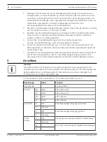
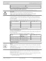
For FAS-420-TT1 and FAS-420-TT2 LEDs, refer to graphic
FAS-420‑TT
Designation
LED
1
Color
Explanation
I
Operation
Green
Operation
II
Fault
Yellow
Fault
–
in the pipe system
–
of a detector module
–
caused by fan failure
III
Main alarm
Red
100% smoke level
Internal alarm
1
Red
66% smoke level
Info alarm
1
Red
33% smoke level
IV
Smoke level display 1 to 10
1
10 yellow
LEDs
Current smoke level
1
All displays doubled on the FAS-420-TT2


