


12
|
Safety Devices and the UPM Controller
ES Series
ES Series
T111970291 (2015/01)
Subject to change without prior notice
The UPM Board includes the following features:
•
ANTI-SHORT CYCLE TIMER
:
5 minute delay on
break timer to prevent compressor short cycling.
•
RANDOM START
:
Each controller has an unique
random start delay ranging from 270 to 300 seconds
on initial power up to reduce the chance of multiple
unit simultaneously starting at the same time after
power up or after a power interruption, thus
avoiding creating large electrical spike.
•
LOW PRESSURE BYPASS TIMER
:
If the
compressor is running and the low pressure switch
opens, the controller will keep the compressor ON
for 120 seconds. After 2 minutes if the low pressure
switch remains open, the controllers will shut down
the compressor and enter a soft lockout. The
compressor will not be energized until the low
pressure switch closes and the anti-short cycle time
delay expires. If the low pressure switch opens 2-4
times in 1 hour, the unit will enter a hard lockout. In
order to exit hard lockout, power to the unit would
need to be reset.
•
BROWNOUT/SURGE/POWER
INTERRUPTION PROTECTION
:
The brownout
protection in the UPM board will shut down the
compressor if the incoming power falls below 18
VAC. The compressor will remain OFF until the
voltage is above 18 VAC and ANTI-SHORT CYCLE
TIMER (300 seconds) times out. The unit will not go
into a hard lockout and does not need to be reset.
•
MALFUNCTION OUTPUT
:
Alarm output is
Normally Open (NO) dry contact.
If pulse is
selected the alarm output will be pulsed. The
fault output will depend on the dip switch
setting for “ALARM”. If it is set to “CONST”, a
constant signal will be produced to indicate a
fault has occurred and the unit requires
inspection to determine the type of fault. If it is
set to “PULSE”, a pulse signal is produced and
a fault code is detected by a remote device
indicating the fault. See L.E.D Fault Indication
below for blink code explanation. The remote
device must have a malfunction detection
capability when the UPM board is set to
“PULSE”.
•
DISPLAY OUTPUT
:
The Display output is a pulse
output connected to the Unit Diagnostic Display
(UDD) and it pulses 24VAC when the unit is in an
lockout alarm condition.
•
TEST DIP SWITCH
:
A test dip switch is provided
to reduce all time delays settings to 10 seconds
during troubleshooting or verification of unit
operation.
•
FREEZE SENSOR
:
T
he freeze sensor input is
active all the time, if a freeze option it not
selected the freeze terminals will need a
jumper. There are two (2) configurable freeze
points, 26°F & 15°F. The unit will enter a soft
lock out until the temperature climbs above
the set point and the anti-short cycle time
delay has expired. The freeze sensor will shut
the compressor output down after 90 seconds
of water flow loss and report a freeze
condition.
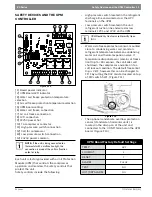
UPM DIP SWITCH DEFAULT POSITION
lockout
4
2
reset
R
Y
alarm
Cont
pulse
test
yes
no
If 24 VAC output is needed R must be wired to
ALR-COM terminal; 24 VAC will be available o
the ALR-OUT terminal when the unit is in the
alarm condition.
NOTE:
Operation of unit in test mode can
lead to accelerated wear and premature
failure of components. The "TEST" switch
must be set back to "NO" after
troubleshooting/servicing.
It is recommended to have a flow switch to
prevent the unit from running if water fl ow is
lost.
NOTE:
If unit is employing a fresh water
system (no anti-freeze protection), it is
extremely important to have the Freeze1
R42 resistor set to 26°F in order to shut
down the unit at the appropriate leaving
water temperature and protect your heat
pump from freezing if a freeze sensor is
included.


