background image

42

en | Subsystem Maintenance

RAID Subsystem DVA-08K | Installation Manual

F.01U.027.797 | V1 | 2006.05

Bosch Security Systems

2.

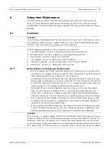
Once the power switches have been turned off, remove the power cables that connect 

the subsystem to the main power. The power connector is found on the left side of each 

power supply module.

3.

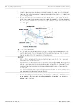
Remove the retention screw: After the power cable has been removed from the power 

connector, remove the retention screw at the upper right side of the PSU rear-end panel. 

The screw is located below the extraction lever, beside the LED indicator, and can be hid-

den from sight.

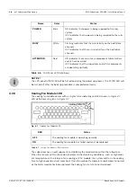
Fig. 6.4

PSU Parts Identification

4.

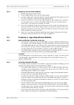
Pull the extraction handle downward: Push the extraction lever at the back of the PSU 

module downwards. This will dislodge the PSU module from the subsystem. Once dis-

lodged, gently pull the PSU module out of the subsystem.

5.

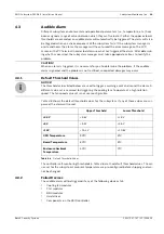
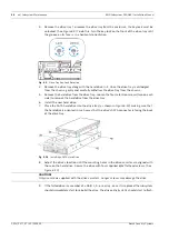
Remove the cooling module: To do this, push the clips on either side of the module rear 

panel together. Then gently pull the cooling module out of the lower level of the PSU 

bracket. (See 

Figure 6.5

)

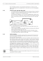
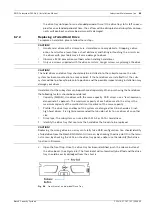
CAUTION! 

When a PSU is pulled out of the chassis, the fan module beneath the PSU is removed 

from the chassis at the same time.

Do not remove the PSU module unless a replacement is readily available. Removing a PSU 

without a replacement will cause severe disruptions to the internal airflow and the sub-

system will overheat, possibly causing irreparable damage to some of the subsystem 

components.

It is recommended that the replacement procedure is completed in less than five (5) min-

utes to prevent the subsystem from overheating.

Содержание DVA-08K

Страница 1: ...RAID Subsystem DVA 08K DVA 08K SCSI Premium Series en Installation Manual ...

Страница 2: ......

Страница 3: ...6 2 5 Hot Swappable Components 16 2 5 1 Hot Swap Capabilities 16 2 5 2 Components 16 2 5 3 Normalized Airflow 16 3 Hardware Installation 17 3 1 Installation Prerequisites 17 3 2 Safety Precautions 17 3 2 1 Precautions and Instructions 17 3 2 2 Static Free Installation 18 3 2 3 BBU Warnings and Precautions 18 3 3 General Installation Procedure 19 3 3 1 Installation Procedure Flowchart 19 3 4 Unpack...

Страница 4: ... 3 2 Selecting a Memory Module 39 6 3 3 DIMM Module Installation 40 6 4 Replacing a Faulty BBU 41 6 5 Replacing a Failed PSU Module 41 6 5 1 Notes on PSU Module Maintenance 41 6 5 2 Replacing the PSU Module 41 6 6 Replacing a Failed Cooling Fan Module 43 6 6 1 Notes on Cooling Fan Module Maintenance 43 6 6 2 Replacing a Cooling Fan Module 44 6 7 Drive Tray Maintenance 44 6 7 1 Notes on Hard Drive ...

Страница 5: ... that during operation all enclosure modules and covers are securely in place Be sure that the rack cabinet into which the subsystem chassis will be installed provides sufficient ventilation channels and airflow circulation around the subsystem Provide a soft clean surface to place your subsystem on before working on it Servicing on a rough surface may damage the exterior of the chassis If it is n...

Страница 6: ...ced radio TV technician for help This device complies with Part 15 of FCC Rules Operation is subjected to the following two conditions 1 this device may not cause harmful interference and 2 this device must accept any interference received including interference that may cause undesired operation This device is in conformity with the EMC CB Certified Worldwide This device meets the requirements of...

Страница 7: ...ing complete RAID configuration and data protection function ality The subsystem s operation is protected by redundant hot swappable power supplies and cooling fan modules Designed for a high level availability all major components are hot replaceable including its Li ION battery and the RAID protected disk drives The subsystem supports high density array capacity by its eight drive bays for SATA ...

Страница 8: ... swappable load sharing power supplies A module slot for a Li ION battery module The front section of the enclosure houses eight 8 hot swap drive bays for SATA II or backward compatible with SATA I hard disk drives The subsystem is shown below Fig 2 1 8 bay SATA RAID Subsystem 2 2 Enclosure Chassis 2 2 1 Chassis Overview The RAID subsystem comes in a 2U metal chassis A backplane board divides the ...

Страница 9: ...D subsystems described in this man ual are shown in Figure 2 3 A description of the front panel component is given below Fig 2 3 Front View The front panel is designed to accommodate the following components Forearm handles with an LCD keypad panel The LCD Panel mounted on the left handle shows system information and provides local access to the firmware embedded configu ration and monitoring util...

Страница 10: ...controller main board and a pre installed DDR DIMM module Power Supply Unit PSU The PSU is used to provide power to the subsystem BBU module A BBU provides the protective implementation to cached data and unless deselected when purchasing the subsystems is installed into the module slot located at the upper left corner of the controller module Cooling fan module The redundant cooling fan module is...

Страница 11: ...ons a mute button and LED status indicators The LCD front panel provides full access to all array configurations and monitoring After powering up the subsystem the initial screen will show the subsystem model name A different name can be manually assigned to the sub system or different drive arrays This will enable easier identification in a topology consisting of numerous arrays Fig 2 7 Front Pan...

Страница 12: ...removed or opened Controller Module Interfaces The subsystems provide external interfaces to host computers and management station s through the RAID controller s rear side faceplate as shown in Figure 2 10 Fig 2 10 Controller Module Faceplate Host Ports SCSI 320 Host Ports Two SCSI 320 host channels connect the subsystem to the host computers equipped with SCSI 320 compatible adapters through the...

Страница 13: ...er of the controller module in the rear of subsystem chassis Please refer to Section 3 Hardware Installation for installation details Fig 2 11 BBU Module In accordance with international transportation regulations the BBU module is only charged to between 35 and 45 of its total capacity when shipped Therefore when powering on the subsystem for the first time the BBU will begin to charge its batter...

Страница 14: ...d only be done if the PSU has failed and needs to be replaced Fig 2 12 PSU Module 2 3 6 Cooling Fan Modules The SATA based RAID subsystem is equipped with two 1U single fan redundant hot swappa ble cooling modules shown in Figure 2 13 One 9 7cm fan is housed in each cooling module These modules have been designed to generate a cooling flow from the front to the rear of the subsystem to extract the...

Страница 15: ...ed RAID subsystem comes with a number of different monitoring methods that provide you with continual updates on the status of the system and individual components The following monitoring features are included in the subsystem 2 4 1 I2C Bus The following subsystem elements are interfaced to the RAID controller over a non user ser viceable I2 C bus Cooling fan modules PSUs Temperature sensors 2 4 ...

Страница 16: ... of hot swappable components A hot swap component is one that can be exchanged while the subsystem is still online without affecting the opera tional integrity of the subsystem These components should only be removed from the sub system when they are being replaced At no other time should these components be removed from the subsystem 2 5 2 Components The following components are all hot swappable...

Страница 17: ...e COM1 port for local terminal emulation access to the array Two 2 power cords are provided for the power connections to the power sources The RJ 45 Ethernet cable for network management connection is a user supplied item Memory module If you wish to change the pre installed memory module a separately purchased module must be installed Please contact your vendor for a different memory module or co...

Страница 18: ...ischarge ESD To prevent ESD damage to any of the components follow these precautions before touching or handling them Discharge the static electricity from your body by wearing an anti static wristband or by touching a grounded metal surface Avoid carpets plastic vinyl and styrofoam in your work area Handle all components by holding their edges or metal frame Avoid touching PCB boards and connecto...

Страница 19: ...ves Installing the subsystem into a rack or cabinet requires at least two 2 people 3 Install drive trays After the hard drives have been installed into the drive trays the drive trays must be installed into the enclosure itself See Section 3 6 Drive Tray Installation 4 Cable connection Use the power cords that came with the subsystem to connect the subsystem to the main power source Use self purch...

Страница 20: ... screwdriver Wrenches may be necessary depending on the rack type Use the included M5 or M6 screws for securing the chassis through its front mounting ears More details about the use of optional slide rails are given in the Installation Guide that came with the slide rail package 3 5 2 Mounting Holes Positions Integrators may design their own brackets or slide rails using the twenty two 22 mount i...

Страница 21: ...rive Tray 2 Open the front flap on the drive tray See Figure 3 4 To open the flap push the release button on the front bezel The front flap will open in an upward direction Fig 3 4 Opening Drive Tray Front Flap 3 Align the drive tray with the slot in which you wish to insert it Make sure that it is resting on the rails inside the module slot Once the drive tray is lined up with the slot gently sli...

Страница 22: ...he subsystem will not be secure 5 Lock the flap into place by turning the key lock until the groove on its face is pointing down vertical orientation See Figure 3 5 Fig 3 5 Drive Tray Key lock Rotation 6 Once all drive trays are installed the RAID subsystem will poll the drive channels and rec ognize the drives and scan them in automatically 7 When powered up you should check the LEDs on drive bez...

Страница 23: ...ub module can be used to keep you informed of system events via a variety of communication methods like email LAN broadcast fax pager MSN messenger ICQ and SMS The sub module runs as an inde pendent program from Bosch RAIDWatch main program The Configuration Client helps prevent blind time and keeps you constantly informed as to the status of the storage management subsystem LEDs Device status ind...

Страница 24: ...igure 4 1 Refer to Table 4 2 for LED definitions When notified by a drive failure message you should check the drive tray indicators to find the correct location of the failed drive Replacing the wrong drive can cause fatal failure of a logical array Fig 4 1 Drive Tray LEDs Component LED s per Unit Total LEDs Definition Drive Trays 2 16 See Section 4 2 2 Drive Tray LEDs Controller Module 5 5 See S...

Страница 25: ...e drive or the drive tray is not properly installed RED indicates drive failure or faults have occurred Table 4 2 Drive Tray LED Definitions LED Name Color Status 1 Controller Ready Green ON Indicates controller is active and operating normally FLASHING Indicates controller initial ization is taking place OFF Controller is not ready for opera tion 2 Hst_Bsy Host Ports Busy Green FLASHING Activitie...

Страница 26: ...as an LED on its faceplate See Figure 4 4 The function is the same as the fifth LED on the controller module The LED is off when the BBU is functioning normally and is able to sustain the cache memory The LED flashes to indicate the BBU is currently charging its battery cells If the LED is illuminating amber the unit may have failed Please contact your system vendor to verify the problem Fig 4 4 B...

Страница 27: ...te button can be used to stop the alarm until the next controller event occurs Fig 4 6 LCD Keypad Panel Color Status Flashing Green The power supply has not been turned on The PSU module LED will blink when the subsystem is connected to a power source but has not been turned on Static Green The PSU is operating normally and experiencing no problems Static Red The PSU has failed and is unable to co...

Страница 28: ...has been replaced the cooling fans return to normal speed Name Color Status POWER Blue ON indicates that power is being supplied to the sub system OFF indicates that no power is being supplied to the sub system BUSY White Flashing indicates that there is activity on the host drive channels OFF indicates that there is no activity on the host drive channels ATTENTION Red ON indicates that one or mor...

Страница 29: ...any of these values are sur passed the alarm will sound The controller self monitoring thresholds in Table 4 8 are the default threshold values The val ues set for the subsystem s ambient temperature are pre configured before shipping and can not be changed 4 3 2 Failed Devices The audible alarm will be triggered if any of the following devices fail Cooling fan modules PSU modules BBU modules Hard...

Страница 30: ...es are monitored through an I2 C serial bus If any of these modules fails the failure will be detected and you will be notified via the various methods described above i NOTICE If the temperature exceeds a preset threshold the BBU charger circuits will stop charging You will then receive a message that says Thermal Shutdown Enter Sleep Mode When the temperature falls back within normal range the b...

Страница 31: ...re drive should have a minimum capacity equivalent to the largest drive that is to be replaced If the capacity of the spare is less than the capacity of the drive to be replaced then the controller will not proceed with the failed drive rebuild 5 2 SCSI Connection Overview The SCSI host ports connect to SCSI 320 host adapters HBA that comply with 320MB s transfer rate and SCSI 3 protocol best capa...

Страница 32: ...twork management connection is a user supplied item Use straight through Ethernet cables with RJ 45 plugs 5 2 3 SCSI Termination Correct SCSI termination procedures require that the last device on the SCSI bus be termi nated If the last device is not terminated or if devices other than the last are terminated erratic SCSI bus behavior may occur An auto detection on board terminator is built into t...

Страница 33: ...ervers or workstations equipped with SCSI HBAs 2 Connect two subsystems on the same host buses for a larger combined capacity 3 Cross link the host ports on subsystem s to clustered servers High availability configurations such as clustering or redundant paths settings can be applied with adequate software control The same logical array can be associated with two or more different host IDs to faci...

Страница 34: ...Use the power cables that came with the subsystem to connect the subsystem to the power outlet separate power sources or UPS devices 2 Turn on the power supply switches for both power supply units 3 The subsystem is now turned on and the self test will start automatically 4 The Power LED on the front LCD panel will turn blue 5 4 4 Power On Status Check Once the subsystem has been powered on the st...

Страница 35: ... panel LCD to show READY or No Host LUN before turning on the host computer Refer to Figure 5 3 on how to read the screens Fig 5 3 The LCD Initial Screen The LCD screen startup sequence is shown and described in the sequence below i NOTICE The subsystem has been designed to run continuously If a hot replaceable component fails the fault can be corrected online This screen appears when the PSUs are...

Страница 36: ...ystem To do this disconnect the cables from both the host and the subsystem 3 Flush the cache Use the Shutdown Controller function to flush all cached data This prepares the RAID subsystem to be powered down 4 Turn off the power Turn off the power switches at the power supply modules Once the RAID subsystem has been powered down other devices that are connected to the subsystem can be powered down...

Страница 37: ... advised that you refer sub system maintenance to a suitably qualified maintenance technician Normalized airflow is directly dependent upon the presence of all subsystem compo nents Even if a subsystem component fails it should not be removed from the sub system until a replacement is readily at hand and can be quickly installed Removing a subsystem component without a replacement can lead to perm...

Страница 38: ...precautions must be strictly adhered to Failure to adhere to these precautions can result in permanent damage to the controller board resulting in lengthy delays Prior to replacing the controller module it is imperative for your own safety to be sure no power is being supplied to the system 6 2 3 Removing the Controller Module To remove the controller module 1 Stop host I Os or host applications t...

Страница 39: ...one Replacement and installation instructions are described fully below The DIMM module is located on the controller board The controller board is a sensitive component and must be treated with care to avoid being damaged 6 3 2 Selecting a Memory Module If the memory module mounted on the controller is going to be replaced the following factors should be considered when purchasing replacement modu...

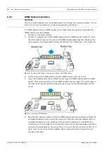
Страница 40: ...ign the DIMM module with the DIMM socket Once aligned gently push the DIMM module into the socket The white clips on the sides of the socket will close automatically and secure the DIMM module into the socket Fig 6 3 Insert the DIMM Module 5 Reinstall the controller module After the DIMM module has been properly installed the controller module must be reinstalled To do this align the controller mo...

Страница 41: ...e Removing a PSU without a replacement will cause severe disruptions to the internal airflow and the sub system will overheat possibly causing irreparable damage to some of the subsystem components PSU bracket Each PSU module is permanently mounted in a two level steel bracket cre ating a single unit The PSU is located in the upper level and a removable cooling fan module is mounted in the lower l...

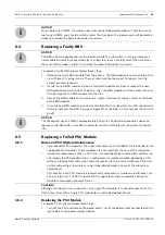
Страница 42: ...r at the back of the PSU module downwards This will dislodge the PSU module from the subsystem Once dis lodged gently pull the PSU module out of the subsystem 5 Remove the cooling module To do this push the clips on either side of the module rear panel together Then gently pull the cooling module out of the lower level of the PSU bracket See Figure 6 5 CAUTION When a PSU is pulled out of the chass...

Страница 43: ... The subsystems are equipped with two redundant hot swappable single blower cooling fan modules located in the lower PSU module slot These cooling fan modules control the internal operational temperature of the subsystem and therefore their working integrity should be maintained at all times Detecting a failed cooling fan module If a cooling fan module fails you can be notified of the failure by t...

Страница 44: ...rive is behind either the left or right forearm handle make sure that the locking mechanism on the side of the handle is first released prior to open ing the handle itself See Figure 6 7 The locking mechanism must also be released in order to close the handle Therefore after the new drive has been installed it will be nec essary to release the locking mechanism on the handle prior to closing it Fi...

Страница 45: ...drive that needs to be replaced 2 Open the front flap Once the drive tray has been identified push the release button at the drive bezel See Figure 6 8 The front bezel will automatically be lifted and the drive tray should be easily dislodged from the chassis Fig 6 8 Front View of an Individual Drive Tray CAUTION Handle hard drives with extreme care Hard drives are very delicate Dropping a drive o...

Страница 46: ...ur retention screws two on each side to remove the hard drive from the drive tray 6 Install the new hard drive 7 Place the SATA hard drive into the drive tray as shown in Figure 6 10 making sure that the hard drive is oriented in such a way that the drive s SATA connector is facing the back of the drive tray Fig 6 10 Installing a SATA Hard Drive 8 Adjust the drive s location until the mounting hol...

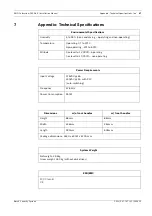
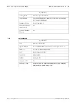
Страница 47: ...rating 0º to 40ºC Non operating 40º to 60ºC Altitude Sea level to 12 000ft operating Sea level to 20 000ft non operating Power Requirements Input Voltage 115VAC 6A 240VAC 3A with PFC auto switching Frequency 47 63Hz Power Consumption 350W Dimensions w o front handles w front handles Height 88mm 88mm Width 446mm 482mm Length 490mm 505mm Package dimensions 344H x 600W x 670D mm System Weight Net wei...

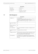
Страница 48: ...nt notification via the Bosch RAIDWatch Manager LAN broadcast email fax MSN ICQ SMS and SNMP traps and RS 232C terminal display Specifications RAID Levels 0 1 0 1 3 5 10 30 50 JBOD and non RAID disk spanning Host OS Compatibil ity Host OS independent supports all major platforms Host Interface 2 SCSI 320 channels via 2 dual stacked VHDCI connectors Host Channels 2 pre configured SCSI 320 host chan...

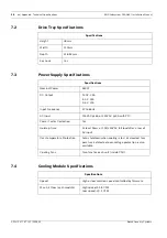
Страница 49: ...DIMM socket Number of LUN s Up to 32 per host ID Multiple Target IDs Host Channel Yes Firmware on Flash Memory Yes Specifications Specifications CPU IBM PowerPC 750CXr Gigabit Ethernet One 10 100BasedT for local or remote management access DIMM Slot One 184 pin DDR DIMM module ASIC 64 bit chipset ASIC266 Flash ROM 32Mbit 4MB NVRAM 32KB with RTC Hardware XOR Yes Real time Clock For event messages w...

Страница 50: ... Output 12 0V 25A 5 0V 25A 3 3V 20A Input Frequency 47 to 63Hz AC Input 115VAC 6A or 240VAC 3A with PFC Power Factor Correction Yes Hold up Time At least 16ms at 115 230VAC full load after a loss of AC input Over temperature Protection Auto shutdown when cooling is lost or elevated tem perature is detected over voltage protection is also available Cooling Fans Two fans for each unit inside PSU Spe...

Страница 51: ...rial cable The Bosch RAIDWatch Manager program using Ethernet connec tion Performance Monitor ing Yes Remote Control and Monitoring Yes Event Notification Yes via Bosch RAIDWatch s sub modules Configuration Client or NPC Management Connec tion In band over Ethernet or RS 232C Configuration on Disk Configuration data stored on disk drives for logical drive assem blies to exist after controller repl...

Страница 52: ...ice via I2 C Interface Yes Automatic Drive Failure Detection Yes Regenerate Logical Drive Parity Yes Bad Block Reassignment Yes Automatic Rebuild upon Failed Drive Replacement Yes Automatic Rebuild on Spare Drives Yes Manual Clone of Suspected Failed Drive Yes Concurrent rebuild on Multiple Drives in a RAID 0 1 Logical Drive Yes Salvage the 2nd Temporarily Failed Drive in a RAID 1 3 or 5 Logical D...

Страница 53: ...le for the RAID subsystem Some of these accessory items come with the subsystem but if damaged or if more accessory items are needed they can be ordered separately Available accessory items are listed below Model Name Description DVA ADTK 000A Drive tray type III bezel and type II LED lightpipe DVA SPKK 050A Drive tray including 500 GB Hitachi SATA drive DVA SPKK 08A Power supply module E2U DDR in...

Страница 54: ...U 027 797 V1 2006 05 Bosch Security Systems DVA ACON VD680A External SCSI round cable VHDCI to VHDCI 0 5 m One included in the shipping package DVA ASRK 28A Slide rails for 21 28 5 deep racks DVA ASRK 36A Slide rails for 23 36 deep racks Model Name Description Table 8 3 Accessories List Cont ...

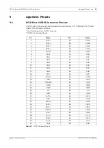
Страница 55: ...rminator Power Pin Name Pin Name 1 SD12 35 SD12 2 SD13 36 SD13 3 SD14 37 SD14 4 SD15 38 SD15 5 SDP1 39 SDP1 6 SD0 40 SD0 7 SD1 41 SD1 8 SD2 42 SD2 9 SD3 43 SD3 10 SD4 44 SD4 11 SD5 45 SD5 12 SD6 46 SD6 13 SD7 47 SD7 14 SDP0 48 SDP0 15 GND 49 GND 16 DIFSENS 50 GND 17 TPWR 51 TPWR 18 TPWR 52 TPWR 19 NC 53 NC 20 GND 54 GND 21 SATN 55 SATN 22 GND 56 GND 23 SBSY 57 SBSY 24 SACK 58 SACK 25 SRST 59 SRST ...

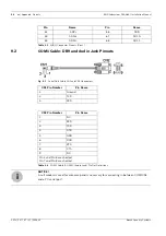
Страница 56: ...SD10 34 SD11 68 SD11 Pin Name Pin Name Table 9 1 VHDCI Connector Pinouts Cont CN1 Pin Number Pin Name 1 Ground 2 TXD 3 RXD CN2 Pin Number Pin Name 1 NC 2 RXD 3 TXD 4 DTR 5 GND 6 DSR 7 RTS 8 CTS 9 NC Pin 4 and Pin 6 are shorted Pin 7 and Pin 8 are shorted Table 9 2 COM 1 Cable RS 232C Audio Jack Pin Out Definitions i NOTICE A null modem is used for wire swap and is necessary for connecting in betwe...

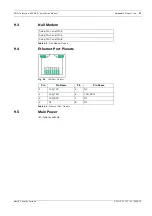
Страница 57: ...05 9 3 Null Modem 9 4 Ethernet Port Pinouts Fig 9 2 LAN Port Pinouts 9 5 Main Power IEC type receptacle Swap Pin 2 and Pin 3 Swap Pin 4 and Pin 6 Swap Pin 7 and Pin 8 Table 9 3 Null Modem Pinouts Pin Pin Name Pin Pin Name 1 LAN_TXP 5 N2 2 LAN_TXN 6 LAN_RXN 3 LAN_RXP 7 N1 4 N2 8 N1 Table 9 4 Ethernet Port Pinouts ...

Страница 58: ...58 en Appendix Pinouts RAID Subsystem DVA 08K Installation Manual F 01U 027 797 V1 2006 05 Bosch Security Systems ...

Страница 59: ...t posts 21 front flap 21 front panel 9 11 fully charged 41 G GUI 15 H handles 44 hard drive 34 37 45 host connection 31 33 host redundancy 33 hot swap mechanism 11 hot swappable 37 components 16 I I2C 23 30 I2C bus 15 input voltage 47 international transportation regulation 13 Internet SCSI 7 iSCSI initiators 31 K Key Lock 46 L LAN Port LED 26 LCD 35 LCD Panel 9 LCD Screen 35 LED 15 M media scan 3...

Страница 60: ...m DVA 08K Installation Manual F 01U 027 797 V1 2006 05 Bosch Security Systems T terminal emulation program 15 terminal management 13 threshold values 29 U under charge 25 V ventilation clearance 18 W warning alarms 48 X XOR 49 ...

Страница 61: ......

Страница 62: ...Bosch Security Systems Robert Koch Straße 100 D 85521 Ottobrunn Germany Telefon 49 89 6290 0 Fax 49 89 6290 1020 www bosch securitysystems com Bosch Security Systems 2006 ...

Отзывы: