


2021.01 | 9
TOW ASSIST INSTALLATION MANUAL
ABS & SWAY MITIGATION SYSTEM
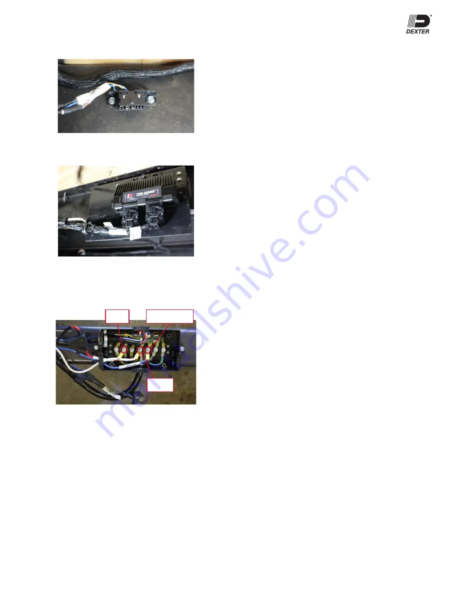
Mount the OBD2 connector securely using appropriate screws per
application.
Secure both harnesses approximately 6” (but no more than 7”)
away from the ECU. This is needed to ensure harness tension is not
transferred to the ECU well as limiting vibration input.
System function requires secure connections at a junction point behind
the tow vehicle connector plug for power (red), ground (white) and brake
request (blue). This illustration is for example only, exact wiring position
will vary by manufacturer and application. For further explanation please
see wiring diagram on page 6.
Brake Request
Ground
Power
ECU Initial Start Up
The Tow Assist system is configured via the OBD2 connector in the
harness. The system configuration kit is available from Dexter and can
be used for multiple applications of varying axle count and wheel sizes.
This kit consists of a 15’ cable to connect the OBD2 plug to the OBD2
connector, a CAN to USB converter unit, and software voucher. The
software requires Windows 10 64-bit operating system. Windows 7 is
supported but not recommended.
At power up, the system will check for the presence of the wheel speed
sensors, magnets, indicator light and wiring harness. Since this is
the initial start the ECU will not be configured and the check will fail
resulting in an Amber fault light.
When the ECU is
CORRECTLY
configured and power is applied, the
system starts as follows:
The indicator light will have two short color alternating bursts.
This is the ECU checking for light presence.
Then the ECU will check for the presence of the sensors.
Then the ECU will check for the magnets. You may be able to hear
the magnets activating for a short burst at each wheel in turn.
Also, one can hear the relays in the ECU activating, at this time.
The indicator light will turn off after the ECU stops clicking.
Apply a valid brake signal to the Blue brake wire and the Tow
Assist will be ready to drive and the indicator light will be green.
The brake signal could be a mom12v application to the
blue wire or a valid signal from a brake controller.
Valid Brake Signal from Brake Controller
Brake controllers available will vary somewhat on the exact signal
produced at standstill. Tow Assist requires a signal that exceeds a
threshold value. This value should be achieved by setting the gain to
‘2’ or higher. This should ensure that a given controller outputs a valid
signal at standstill. If Tow Assist does not go into normal operation do
the following until the system indicator light is green:
1. Press and hold the brake pedal for at least 2 seconds.
2. Press and hold the brake override switch for at least 2 seconds.
3. Increase the gain setting slightly.
4. If Tow Assist does not become active, check trailer plug
connections, wire and power supply to the Tow Assist and
repeat steps above.
Configuration Software
Following the physical installation of the Tow Assist system, the ECU
requires configuration before the ABS and Sway Mitigation will function.
The configuration steps in this section identify how to use the software
to assign axle count, tire size and manufacturer vehicle identification
number.
The following information is needed to configure an ECU:
Number of axles
Tire size; Aspect ratio, width, wheel diameter so the software can
calculate the rolling tire circumference for the ECU.
VIN number (if desired to be input into ECU)
Install the software and setup per the cable kit installation instructions
(059-A46-00) available at www.dexteraxle.com.
Configuration File Setup
Setup needs to be tested on the first trailer before saving into a
configuration file on the PC with an appropriate identifying name. This
will allow more straightforward use by production personnel for system
configuration. The production personnel will select the proper parameter
file and load it into the configuration tool. To set up the parameter file,
follow these instructions:
1. Start the software on a computer by clicking the Dexter Tow
Assist icon.