


A D00 A49 029
|
2017-06-09
Robert Bosch Engineering and Business Solutions Private Limited
3.7
Calibration
The gas sensors that are available as part of the BOSCH CLIMO are pre-calibrated by the sensor manufacturer
and should have expected response to change in ambient air conditions within the first 7 days, post installation.
However, these gas sensors are known to drift over time. Hence they require frequent recalibration. BOSCH CLIMO
uses the following 2 methods for recalibration:
•
Regular recalibration cycles or field recalibration:
This is done by using data from an EPA graded instrument,
co-located along with or available in the near vicinity of the BOSCH CLIMO. This recalibration is handled
remotely using the remote device management platform.
•
In-house recalibration:
This is carried out by unmounting the device and recalibrating it in a laboratory environment
with NIST certified calibration gases or completely replacing the sensor to have a new one in place of the existing
one.
i
For use cases which require greater accuracy of data, frequent recalibration would be required. The best suited
recalibration cycle can be defined by observing the trend of sensor data from the BOSCH CLIMO in its current
deployment location for the first few days.
i
Environment and particulate matter sensors do not exhibit any behavioral drift over time and hence may not
need regular recalibration cycles.
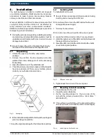
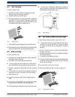
3.8
Health indicators
You can know the device is functional by checking the red LED indicator. Blinking of this LED, indicates that there
is a proper connection of the BOSCH CLIMO device with cloud and the data is being transmitted successfully.
3.9
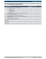
Pre installation Acceptance checklist
i
Take the print out of the checklists, sign and store it for every unit.
Sl. No.
Description
Test Passed
(Yes/No/NA)
Comments
1
Availability of product handling or installation safety precaution (ex. hand
gloves, ladder, helmet, safety belt)
2
Availability of ESD protection for SIM installation
3
Device Serial number
4
Device Mac ID
5
Location
6
Latt and Long
7
SIM card number
8
SIM ID Number
9
SIM must be industrial grade and WCDMA/3G MICRO SIM (3ff) (Micro-SIM
(3ff) industrialization grade robust or super-robust plastic type with operating
temperature -40
ˇ
c to 105
ˇ
c)
10
Availability of Ethernet mating connector along with cable
11
Availability of Ethernet connection at location
12
Confirmation of signal strength from Service provider at the installation
location
13
Availability and verification of dispatch checklist
14
Physical verification of the complete product and accessory kit
15
Test report available
16
Torque controlled Tools availability for installation
17
Installation manual (soft copy)
18
Availability of DC/AC power socket
19
Ensure the proper voltage (12v DC/230v ac)
20
Ensure no obstruction in north and south direction at the installation pole
21
Installation height must be within 8 to 12 feet
22
Date and time of installation
en
10 | Pre Installation
Содержание CLIMO A D00 A40 103
Страница 1: ...MicroClimateMonitoringSystem BOSCH CLIMO ...