background image


 Installation Manual


Bosch Climate 5000 AA Series Split Type Ductless Air Conditioner / Heat Pump 


| 17


Bosch Thermotechnology Corp. 

|

 01.2017


 Data subject to change

6     Outdoor unit installation

Step 1: Select installation location

Before installing the outdoor unit, you must choose an appropriate location. The 
following are standards that will help you choose an appropriate location for the unit.


Proper installation locations meet the following standards:


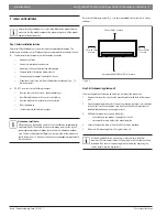
Meets all spatial minimum requirements shown in Installation Space 
Requirements ( Fig. 20 )

e

v

o

b

a )

ni

4

2( 

mc

0

6

60cm (24in) 

on righ

t

30cm (12in) 

on left

200cm (79in) 

in fron

t

30cm (12in) 

from back wall

Figure 20


Good air circulation and ventilation


Firm and solid—the location can support the unit and will not vibrate


Noise from the unit will not disturb others


Protected from prolonged periods of direct sunlight or rain


DO NOT install unit in the following locations:


Near an obstacle that will block air inlets and outlets


Near a public street, crowded areas, or where noise from the unit will 
disturb others


Near animals or plants that will be harmed by hot air discharge


Near any source of combustible gas


In a location that is exposed to large amounts of dust


In a location exposed to excessive amounts of salty air


NOTICE


If the unit is exposed to heavy wind: Install unit so that air 
outlet fan is at a 90° angle to the direction of the wind. If 
needed, build a barrier in front of the unit to protect it from 
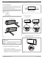
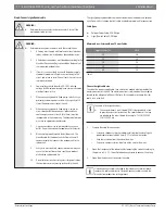
extremely heavy winds. See Fig. 21 and Fig. 22.

Strong wind

Strong wind

Figure 21

Strong 
wind

Wind Baffle

Figure 22

    NOTICE


If the unit is frequently exposed to heavy rain or snow:


Build a shelter above the unit it to protect it from the 
rain or snow. Be careful not to obstruct air flow around 
the unit.


This unit is not designed for application in areas frequently 
exposed to salty air (seaside) conditions..

Step 2: Install drain joint

Heat pump units require a drain joint. Before bolting the outdoor unit in place, you 
must install the drain joint at the bottom of the unit. Note that there are two diff erent 
types of drain joints depending on the type of outdoor unit.

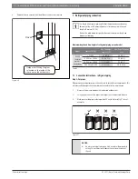
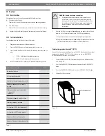
If the drain joint comes with a rubber seal (see Fig. 23, pos. A ), do the following: 

1. 

Fit the rubber seal on the end of the drain joint that will connect to the 
outdoor unit. 

2. 

Insert the drain joint into the hole in the base pan of the unit. 

Содержание Climate 5000 AAS-009-0CS

Страница 1: ...Bosch Split Type Ductless Air Conditioner Heat Pump Climate 5000 AA Series Installation Manual ...

Страница 2: ...2 Bosch Climate 5000 AA Series Split Type Ductless Air Conditioner Heat Pump Installation Manual 01 2017 Bosch Thermotechnology Corp Data subject to change ...

Страница 3: ...on 9 6 Outdoor unit installation 17 7 Refrigerant piping connection 22 7 1 Connection instructions refrigerant piping 22 7 2 Connecting piping to indoor unit 25 7 3 Connecting tubing to outdoor unit 25 8 Air evacuation 26 8 1 Preparations and precautions 26 8 2 Evacuation instructions 26 8 3 Adding refrigerant 27 9 Electrical and gas leak checks 28 9 1 Electrical safety checks 28 9 2 Gas leak chec...

Страница 4: ...ngth of the power supply cord or use an extension cord to power the unit Do not share the electrical outlet with other appliances Improper or insufficient power supply can cause fire or electrical shock WARNING When connecting refrigerant piping do not let substances or gases other than the specified refrigerant enter the unit The presence of other gases or substances will lower the unit s capacit...

Страница 5: ...t be replaced by the manufacturer its service agent or similarly qualified persons such as a licensed electrician in order to avoid a hazard The product must be properly grounded at the time of installation or electrical shock may occur CAUTION For units that have an auxiliary electric heater do not install the unit within 1 meter 3 feet of any combustible materials Do not install the unit in a lo...

Страница 6: ...IONER CS78421 548 754 IMPORTANT NOTE Read this manual carefully before installing or operating your new air conditioning unit Make sure to save this manual for future reference Owner s Manual Aurora Series All Model Numbers INVERTER SPLIT TYPE ROOM AIR CONDITIONER CS78421 548 754 IMPORTANT NOTE Read this manual carefully before installing or operating your new air conditioning unit Make sure to sa...

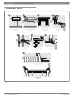
Страница 7: ...lation Summary Indoor Unit Mount Indoor Unit Page 16 STEP8 Wrap Piping and Cable Page 15 1 2 3 Connect Piping Page 25 Connect Wiring Page 14 Prepare Drain Hose Page 13 5 6 7 8 9 Select Installation Location Page 9 Attach Mounting Plate Page 9 Drill Wall Hole Page 10 Determine Wall Hole Position Page 9 1 2 3 4 12cm 4 75in 183cm 72in 12cm 4 75in 15cm 5 9in Figure 1 ...

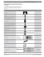
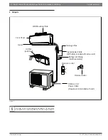
Страница 8: ...efrigerant Piping Sold Separately Signal power Cable 32ft cable included with indoor unit Remote Control Drainage Pipe Louver Remote Holder Front Panel Outdoor Unit Power Cable Required not included with unit Air filter pull it out Figure 2 Illustrations in this manual are for explanatory purposes The actual shape of your indoor unit may be slightly different The actual shape shall prevail ...

Страница 9: ...ve ample room for a wall hole see Drill wall hole for connective piping step for the signal power cable and refrigerant piping that connect the indoor and outdoor units The default position for all piping is the right side of the indoor unit while facing the unit However the unit can accommodate piping to both the left and right Refer to the following diagram Fig 3 to ensure proper distance from w...

Страница 10: ... help seal it when you finish the installation process CAUTION When drilling the wall hole make sure to avoid wires plumbing and other sensitive components Wall Indoor Outdoor m m 7 5 0 2 0 3in Figure 4 Mounting plate dimensions Different models have different mounting plates In order to ensure that you have ample room to mount the indoor unit the diagrams to the right show different types of mounting...

Страница 11: ...r of indoor unit Figure 8 NOTICE Be extremely careful not to crimp or damage the piping while bending them away from the unit Any deformations in the piping will affect the unit s performance If refrigerant piping is already embedded in the wall do the following Step 1 Hook the indoor unit on the mounting plate Keep in mind that the hooks on the mounting plate are smaller than the holes on the bac...

Страница 12: ...ole relative to the mounting plate choose the side from which the piping will exit the unit 2 If the wall hole is behind the unit keep the knock out panel in place If the wall hole is to the side of the indoor unit remove the plastic knock out panel from that side of the unit See Fig 14 This will create a slot through which your piping can exit the unit Use needle nose pliers if the plastic panel ...

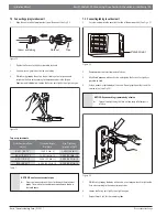
Страница 13: ...m pipe insulation to prevent condensation 5 Remove the air filter and pour a small amount of water into the drain pan to make sure that water flows from the unit smoothly If not make adjustments and test again to see if the condensate will flow freely Make sure to arrange the drain hose according to Fig 15 16 DO NOT kink the drain hose DO NOT create a water trap DO NOT put the end of drain hose in wa...

Страница 14: ...nit to the indoor unit 9 Every wire must be firmly connected Loose wiring can cause the terminal to overheat resulting in product malfunction and possible fire 10 Do not let wires touch or rest against refrigerant tubing the compressor or any moving parts within the unit The signal power cable enables communication between the indoor and outdoor units You must first choose the right cable size before...

Страница 15: ...nding terminal CAUTION Do not mix up live and wires not used This is dangerous and can cause the air conditioning unit to malfunction 8 After checking to make sure every connection is secure use the cable clamp to fasten the signal power cable to the unit Screw the cable clamp down tightly 9 Replace the wire cover on the front of the unit and the plastic panel on the back The wiring connection pro...

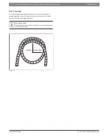
Страница 16: ...ive piping to the outdoor unit do the following 1 If you have already passed the refrigerant piping through the hole in the wall proceed to Step 4 2 Double check that the ends of the refrigerant pipes are sealed to prevent dirt or foreign materials from entering the pipes 3 Carefully pass the wrapped bundle of refrigerant pipes drain hose and signal power wire through the hole in the wall 4 Hook t...

Страница 17: ...s that will be harmed by hot air discharge Near any source of combustible gas In a location that is exposed to large amounts of dust In a location exposed to excessive amounts of salty air NOTICE If the unit is exposed to heavy wind Install unit so that air outlet fan is at a 90 angle to the direction of the wind If needed build a barrier in front of the unit to protect it from extremely heavy win...

Страница 18: ...e If the drain joint doesn t come with a rubber seal see Fig 23 pos B do the following 1 Insert the drain joint into the hole in the base pan of the unit The drain joint will click in place 2 Connect a drain hose extension not included to the drain joint to redirect water from the unit during heating mode NOTICE In cold climates make sure that the drain hose is as vertical as possible to ensure sw...

Страница 19: ...ding to the dimensions below WARNING Never mount this unit directly on the ground It must be anchored according to the guidance provided in these instructions and or local building codes W A B D Air inlet Air outlet Air inlet Figure 24 Outdoor Model OutdoorUnitDimensions mm in MountingDimensions W x H x D Distance A mm in Distance B mm in Climate 5000 AAS 009 0CS Climate 5000 AAS 009 1CS 770x555x3...

Страница 20: ...ncrete eye protection is recommended at all times If you will install the unit on a wall mounted bracket do the following CAUTION Before installing a wall mounted unit make sure that the wall is made of solid brick concrete or of similarly strong material The wall must be able to support at least four times the weight of the unit 1 Mark the position of bracket holes based on dimensions in the Unit...

Страница 21: ...r service disconnect non fused 7 Only connect the unit to an individual branch dedicated circuit Do not connect another appliance to that circuit 8 Make sure to properly ground the outdoor unit 9 Every wire must be firmly connected Loose wiring can cause the terminal to overheat resulting in product malfunction and possible fire 10 Do not let wires touch or rest against refrigerant tubing the compre...

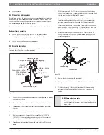
Страница 22: ... unit model Model Capacity BTU h Max Equivalent Length m ft Max Height Variation m ft R410A Inverter Split Air Conditioner 15 000 25 82ft 10 33ft 15 000 to 24 000 30 98 5ft 20 66ft 24 000 to 36 000 50 164ft 25 82ft 36 000 to 60 000 65 213ft 30 98 5ft Table 5 7 1 Connection instructions refrigerant piping Step 1 Cut pipes When preparing refrigerant pipes take extra care to cut and flare them properl...

Страница 23: ...hey are facing in the proper direction because you can t put them on or change their direction after flaring See Fig 29 Flare nut Copper pipe Figure 29 4 Remove tape from ends of pipe when ready to perform flaring work 5 Clamp flaring block on the end of the pipe The end of the pipe must extend beyond the edge of the flare form in accordance with the dimensions shown in the Table 6 Figure 30 Piping ex...

Страница 24: ...tep 4 Connect pipes When connecting refrigerant pipes be careful not to use excessive torque or to deform the piping in any way You should first connect the low pressure suction pipe then the high pressure pipe liquid line Minimum Bend Radius When bending connective refrigerant piping the minimum bending radius is 10cm 4in See Fig 32 10cm 4in Radius Figure 32 ...

Страница 25: ...t 2 600 19 18lb ft Ø 12 7 Ø 0 5 3 500 25 8lb ft 3 600 26 55lb ft Ø 16 Ø 0 63 4 500 33 19lb ft 4 700 34 67lb ft Table 7 NOTICE Do not use excessive torque Excessive force can break the nut or damage the refrigerant piping You must not exceed torque requirements shown in the table above 7 3 Connecting tubing to outdoor unit 1 Unscrew and remove the cover on the side of the outdoor unit See Fig 35 Va...

Страница 26: ...uge Keep the High Pressure side closed 4 Turn on the vacuum pump to evacuate the system 5 Run the vacuum until the Compound Meter reads 76cmHg 29 92 Hg 101 kPa It is recommended to use a micron gauge run the vacuum until the micron gauge reads 350 to 500 microns or less 6 Close the Low Pressure side of the manifold gauge and turn off the vacuum pump 7 Wait for approximately 10 to 15 minutes then ch...

Страница 27: ...5 In other areas the standard pipe length is 5m 16 The additional refrigerant to be charged can be calculated using the following formula Additional refrigerant per pipe length ConnectivePipe AirPurging Additional Refrigerant Standard pipe length Vacuum Pump N A Standard pipe length Vacuum Pump Liquid Side Ø 6 35 ø 0 25 Inverter R410A Pipe length standard length x 15g m Pipe length standard length...

Страница 28: ...kage During the Test Run use an electroprobe and multimeter to perform a comprehensive electrical leakage test If electrical leakage is detected turn off the unit immediately and call a licensed electrician to find and resolve the cause of the leakage This may not be required for some locations in the US WARNING Risk of electric shock All wiring must comply with local and national electrical codes...

Страница 29: ...in hose All piping is properly insulated Unit performs COOL function properly Unit performs HEAT function properly Indoor unit louvers rotate properly Indoor unit responds to remote controller Table 9 WARNING Double check pipe connections During operation the pressure of the refrigerant circuit will increase This may reveal leaks that were not present during your initial leak check Take time durin...

Страница 30: ...osal of recyclable products Refrigerant At the end of the service life of this appliance and prior to it s environmental disposal a person qualified to work with refrigerant circuits must recover the refrigerant from within the sealed system WARNING Improper disposal of this appliance endangers your health and is bad for the environment Hazardous substances may leak into the ground water and enter ...

Страница 31: ... 1 2 ON ENC3 F1 0 F 0 F 0 F 0 F NETADDRESS CODE 0 15 16 31 32 47 48 63 725 6 77 1 FOR SETTING NETADDRESS CCM Comm Bus To CCM Comm Bus or 485 Wire controller To Randomly Connected Wire controller To Remote Switch To Remote Alarm 4 3 MULTI FUNCTION CONTROLBOARD element is optional the actual shape shall prevail This symbol indicates the INDOOR UNIT OUTDOOR UNIT JX1 1 2 3 SWING MOTOR1 5 M CN19 M CN22...

Страница 32: ...2 1 225 81 7 3 2 N 9 32 5 6833 5 8 Y G 1 Y G AMBIENT TEMP SENSOR DISCHARGE TEMP SENSOR CN 21 CONDENSER TEMP SENSOR Y G CN 1A Y G Y G CN4_1 CN4_2 CN4_3 CN4_4 REACTOR CAPACITOR BROWN BLACK BROWN BLACK BLACK BROWN BLACK BROWN Y G 2 2 BLACK W V RED BLUE U 5 5 52 1 52 1 L A N O I T P O T N I O J T S A F NOTE the connection wires for reactor and capacitor should be in the same colors black or brown Note...

Страница 33: ...Installation Manual Bosch Climate 5000 AA Series Split Type Ductless Air Conditioner Heat Pump 33 Bosch Thermotechnology Corp 01 2017 Data subject to change ...

Страница 34: ...34 Bosch Climate 5000 AA Series Split Type Ductless Air Conditioner Heat Pump Installation Manual 01 2017 Bosch Thermotechnology Corp Data subject to change ...

Страница 35: ...Installation Manual Bosch Climate 5000 AA Series Split Type Ductless Air Conditioner Heat Pump 35 Bosch Thermotechnology Corp 01 2017 Data subject to change ...

Страница 36: ...United States and Canada Bosch Thermotechnology Corp 50 Wentworth Avenue Londonderry NH 03053 Tel 866 642 3198 Fax 954 776 5529 www boschheatingandcooling com BTC 770001102 C 01 2017 ...

Отзывы: