


1 689 975 197 (2006-09-22)
Robert Bosch GmbH
en
10
ACS 500
5.
Calibration and customer service menu
The calibration and customer service menu allows you
to select various sub-menus, which can be called up for
configuration, repair or function tests after a repair. Some
of these sub-menus can also be called up in the main menu
under "
Service
" or "
Configuration
".
5.1
Entering the calibration and customer service
menu
Procedure:
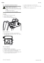
1. Connect mains lead.
2. Turn on ACS 500 using master switch. After turning
on, the following appears in the display on the control/
display unit:
BOSCH
ACS 500
V1.00 deu
17.03.2005
15:19
V
3. Simultaneously press and hold <
C
> and <
E
> keys.
After 5 seconds, the password prompt appears on the
control/display unit:
ENTER PASSWORD
----
4. Enter password (see section 5.2) and confirm your entry
with <
V
>.
5.
Calibration and customer service menu
overview
Password Beschreibung
5465
Menu for updating the language database.
8439
Display menu for force and pressure sensor output
voltages.
8463
Menu for time and date setting
1)
.
5264
Menu for changing language
1)
.
7272
System parameter menu.
3358
Menu for resetting system parameters.
2668
Menu for resetting counters.
8266
Display menu for all counters.
3282
Menu for entry of workshop address
1)
.
7732
Menu for setting the offset for the filling hoses
2)
.
3477
Menu for checking the control/display unit.
8272
Menu for calibration of force and pressure sensors
2)
.
1)
Menus are also available in the main menu under "Configuration".
2)
Menu is also available in the main menu under "Service" with the
password '1958'.
5.
Description of calibration and customer service
menu
5..1 Menu for updating the language database
Menu for updating additional language variations for the
ACS 500. After selecting the menu, the customer service PC
starts to establish a connection to the ACS. The customer
service PC does not load the software until the connection
has been successfully established.
5.. Display menu for force and pressure sensor
output voltages
Display for force and pressure sensor output voltages
Pressing <
> shows the output values for the relevant
sensors in grammes and mbar on the display.
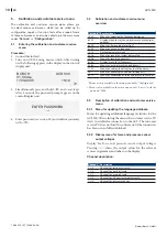
Channel description:
Channel
Description
CH 0
Channel for refrigerant scale
CH 1
Channel for fresh oil scale
CH 2
Channel for used oil scale
CH 3
Channel for UV contrast medium scale
CH 4
Channel for pressure sensor


