Installation (only for approved contractors)
37
Tronic 4000 T – 6721843807 (2022/06)
▶ Use suitable connection accessories for the hydraulic
connection of the appliance.
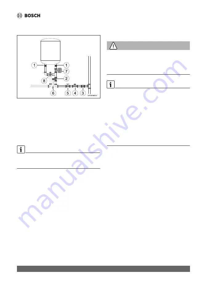
Fig. 11
[1] Galvanic insulation
[2] Pressure relief valve
[3] Non-return valve
[4] Reducer valve
[5] Cut-off Valve
[6] Drainage connection
[7] Expansion vessel
[8] Mixing valve
To avoid problems caused by sudden pressure changes in the
supply system, it is advisable to assemble a check valve
upstream of the appliance.
If there is a risk of freezing:
▶ Disconnect the appliance from the electricity.
▶ Vent the appliance (
chapter 4.6).
5.5
Pressure-relief valve
▶ Install the pressure relief valve on the water inlet of the
appliance.
WARNING
Risk of damage to property!
▶ Never obstruct the vent pipe of the pressure relief valve.
▶ Never install any accessory between the pressure relief
valve and the cold water inlet (right side) of the electric
DHW cylinder.
If the water inlet pressure is between 1.5 and 3 bar, it is not
necessary to install a pressure reducing valve.
If the water inlet pressure is above these values, it is necessary:
▶ to install a pressure reducing valve (Fig. 11, [4]). The
pressure relief valve will activate whenever the water
pressure in the appliance is above 8 bar (± 1 bar), for
which reason it is necessary to plan a way of draining off
this water.
▶ install an expansion vessel (Fig. 11, [7]) to stop the
pressure relief valve opening so frequently. The volume of
the expansion vessel should be equivalent to 5% of the
volume of the appliance.
Содержание 100 EBP
Страница 173: ...Технички информации 173 Tronic 4000 T 6721843807 2022 06 9 2 Дијаграм на ожичување Сл 13 Дијаграм на поврзување ...
Страница 281: ...Informacioni teknik 281 Tronic 4000 T 6721843807 2022 06 9 2 Skema elektrike fig 13 Skema e lidhjeve ...
Страница 308: ...Bosch Thermotechnik GmbH Junkersstrasse 20 24 D 73249 Wernau www bosch thermotechnology com ...


