

PLEASE READ AND SAVE THESE
IMPORTANT SAFETY INSTRUCTIONS
F E AT U R E S - O P E R AT I O N S
F E AT U R E S - O P E R AT I O N S
When using electrical appliances, basic safety precautions
should always be taken including the following:
1. Read all instructions before using this appliance.
2. Use fan only for purposes described in the instruction
manual.
3. To protect against electrical shock do not immerse unit,
plug or cord in water or spray with liquids. Plug the
appliance directly into a 120V AC electrical outlet.
4. Close supervision is necessary when any appliance is
used by or near children.
5. Unplug from outlet when not in use, when moving
fan from one location to another, before putting on
or taking off parts and before cleaning.
6. Avoid contact with moving parts.
7. Do not operate in the presence of explosive and/or
flammable fumes.
8. To avoid fire hazard, NEVER place the cord under
rugs or any parts near an open flame, cooking or
other heating appliance.
9. Do not operate any appliance with a damaged cord
or plug after the appliance malfunctions, or has been
dropped/damaged in any manner. Discard fan or
return to an authorized service facility for
examination and/or repair.
10. The use of attachments not recommended or sold by
the appliance manufacturer may cause hazards.
11. Do not use outdoors.
12. Do not let the cord hang over the edge of a table,
counter or come in contact with hot surfaces or leave
exposed to high traffic areas.
13. To disconnect, grip plug and pull from wall outlet.
Never yank on cord.
14. Always use on a dry, level surface.
15. Do not operate fan until fully assembled with all
parts properly in place.
16. This product is intended for household use ONLY and
not for commercial or industrial applications.
17.
WARNING:
To reduce the risk of fire or electric
shock, do not use this fan with any solid-state speed
control device.
PLEASE READ AND SAVE
THESE IMPORTANT
SAFETY INSTRUCTIONS
INSTALLATION INSTRUCTIONS
Carefully unpack contents from carton.
FOR DOUBLE-HUNG AND SLIDER
WINDOWS
1. Set the fan into your window opening (note that the
window screen does not have to be removed or left open.)
2. If the fan does not fit snugly to the top and bottom of
the window casing, attach the Extender Panel(s) and
adjust the built in extender screen until the fan fits
safely in your window. (See Figure 2)
3. To keep the fan in place, carefully close the window
so that the bottom edge of the window rests on the
flat surface on top of the fan.
NOTE:
FOR SLIDER WINDOWS, SET THE FAN VERTICALLY
IN YOUR WINDOW OPENING WITH THE LEFT SIDE OF THE
FAN SITUATED ON THE BOTTOM AND THE BUILT-IN
EXTENDER SCREEN FACING UPWARDS.
WARNING:
BE SURE FAN IS SECURELY INSTALLED IN
YOUR WINDOW AT ALL TIMES. DO NOT LEAN OR PUSH
ON FAN WHILE IT IS IN THE WINDOW.
OPERATING INSTRUCTIONS
1. Plug cord into any standard 120 volt AC outlet.
2. To turn the fan on and control the speed, press the
mode button. Note that pressing the mode button will
allow you to cycle through the speed setting (High=3,
Med=2, Low=1) as well as the Automatic Thermostat
Temperature settings (Auto High = A3, Auto Medium =
A2, Auto Low = A1). 0 indicates the Off position.
3. Set the airflow direction by sliding the fan directional
switches located above each fan blade. Note that the
fan blades work independently from one another
and can be used for air intake (bring fresh air in
from outside), exhaust (push air out from within the
room) or exchange (cycles air in and out of the room
simultaneously).
AUTO MODE
Your fan is equipped with a Programmable Digital
Thermostat that will automatically turn the fan ON and
OFF depending upon the preset comfort temperature.
This is ideal for night time operation when temperatures
can drop below comfort levels.
For example, if you set your fan to 75 degrees and the
temperature drops to 74 degrees, the fan will
automatically turn off. The fan will automatically turn on
again when the room temperature exceeds the set
temperature.
SETTING AUTO MODE
1. Press the Mode button to scroll to the desired auto
speed setting (A3, A2, or A1).
2. Choose the desired temperature setting by pressing
the Temp Up (+) or Temp Down (-) buttons. You may
select a temperature between 60 and 80 degrees
Fahrenheit. Once the desired temperature is set, the
digital display will return to show the ambient room
temperature. View the set temperature by pressing
either the Temp Up (+) or Temp Down (-) buttons.
IMPORTANT:
If the fan does not start in the Auto
mode, please be sure that the set temperature is below
the current room temperature. Lower the set temperature
if you would like the fan to start or switch over to the
manual speed modes.
SETTING THE TIMER
1. Hold both the Temp Up (+) and Temp Down (-)
buttons down until the digital display flashes “00”.
2. Press the (+) or (-) buttons to change time in 1 hour
increments. Note selection ranges from 1 to 16
hours. When in the timer mode, the time remaining
will be displayed.
NOTE:
If Timer is set when fan is ON, the time displayed
will turn the fan OFF once elapsed. If Timer is set when
fan is OFF, the time displayed will turn the fan ON. (The
default ON speed setting is Manual Low).
NOTE:
Timer function can be turned off by pressing the
MODE key at any time.
REMOTE CONTROL
This unit includes two (2) AAA batteries, 1.5V.
Battery Replacement
a) Locate the battery cover on the back of the remote
control handset. Slide the battery cover off with your
thumb.
b) Remove old batteries.
c) Insert two new batteries, pressing them firmly into
their slot.
d) Replace the battery cover.
NOTES:
• Do not mix old and new batteries.
• Do not mix alkaline, standard (carbon-zinc), or
rechargeable (nickel-cadmium) batteries.
• Replace all batteries of a set at the same time.
• Clean the battery contacts and the devices’ contacts
prior to installing the batteries.
• Remove the batteries from the equipment when it is
not being used for an extended period of time.
• Remove the used batteries promptly.
FCC STATEMENT
Potential for Radio/Television interference
This product has been tested and found to comply with
the limits for a Class B digital device, pursuant to part 15
of the FCC rules.
These limits are designed to provide reasonable
protection against harmful interference in a residential
installation. The product generates, uses, and can radiate
radio frequency energy and, if not installed and used in
accordance with the instructions, may cause harmful
interference to radio communications. However, there is
no guarantee that the interference will not occur in a
particular installation. If the product does cause harmful
interference to radio or television reception, which can be
determined by turning the product on or off, the user is
encouraged to try to correct the interference by one or
more of the following measures:
• Reorient or relocate the receiving antenna.
• Increase the separation between the product and the
receiver.
• Connect the product into an outlet on a circuit
different from that to which the receiver is
connected.
• Consult the dealer or an experienced radio/TV
technician for help.
Changes or modifications not expressly approved by the
party responsible for compliance could void the user’s
authority to operate the equipment.
THIS APPLIANCE HAS A POLARIZED PLUG (one blade is wider than the
other). To reduce the risk of electric shock, this plug is intended to fit in
a polarized outlet only one way. If the plug does not fit fully in the
outlet, reverse the plug. If it still does not fit, contact a qualified
electrician to install the proper outlet.
DO NOT ATTEMPT TO MODIFY THIS PLUG OR DEFEAT THIS
SAFETY FEATURE IN ANY WAY.
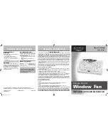
Figure 2
FRONT VIEW
LEFT
Extra Extender Panels 4.25
inches (10cm) - 2 pieces
included in your box
RIGHT
Built-in Extender, pull
out up to 7 inches
(17cm)
UNIT’S LENGTH
A. Front Grill
B. Control Panel
C. Mode Button
D. LED Display
E. Temp Up (+)
F. Temp Down (-)
G. Fan Directional
Switches (2)
H. Built-in Extender
Screen
I. Extender Locks (2)
J. Extender
Panels
(2) (not shown)
K. Remote Control
A
B
G
C D
G
H
J
E F
Figure 1
I
I
K
BORGW2100R_09EM1.indd 2
BORGW2100R_09EM1.indd 2
11/17/09 11:07:06 AM
11/17/09 11:07:06 AM


