bora PT11UMEN-000 Скачать руководство пользователя страница 16

EN

16

Installation

www.bora.com

1

L1

L2

2

3

N

PE

220 - 240 V~

220 - 240 V~

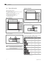
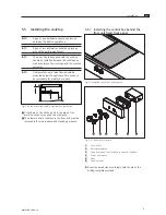
Fig. 5.16 Connection diagram 2-phase

1

L1

2

3

N

PE

220 - 240 V~

Fig. 5.17 Connection diagram 1-phase

X

X

Create the connection between the cooktop and the 

control box.

X

X

Verify that the installation was done correctly.

X

X

Switch on the main switch/automatic circuit breaker.

X

X

Put the cooktop into operation  

(see the Operation section).

X

X

Check all the functions are working correctly.

5.7  Handover to user

Once installation is done:

X

X

Explain the important functions to the user.

X

X

Explain all safety-relevant aspects of operation and 

handling to the user.

X

X

Provide the user with the accessories and operating 

and installation instructions to be kept in a safe place.

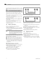
Connecting the heating element to the control 

box

INFO 

Never bend the temperature sensor line. 

Connect the colour-coded temperature sensor to the  

bottom of the Tepan cooktop using the relevant slot.

X

X

Remove the cover plate of the temperature sensor slot 

by pushing the springs together.

X

X

Insert the corresponding temperature sensor into the 

matching coloured slot.

X

X

Ensure that the temperature sensor is engaged in the 

slot straight.

X

X

To secure the temperature sensor, insert the cover 

plate from the back into the slot.

X

X

Ensure that the cover plates are positioned tightly 

against the housing.

5.6  Power connection

X

X

Observe all safety and warning information  

(see the Safety chapter).

X

X

Observe all national and regional laws and regulations 

as well as the supplementary regulations of the local 

utility companies.

INFO 

INFO  The power connection may only be es-

tablished by a certified specialist. He/she also 

assumes responsibility for the proper installa-

tion and commissioning.

The power supply line for use (pre-assembled) must be at 

least Type H05VV-F or H05VVH2-F.

Q

Q

Cross-section: 3G2.5 mm² with 1-phase connection

Q

Q

Cross-section: 4G2.5 mm² with 2-phase connection

Q

Q

If the connection line has been damaged this must be 

replaced by a special connection line. This may only 

be done by an authorized member of the After Sales 

Service team.

Establishing the power connection

X

X

Switch off the main switch/automatic circuit breaker 

before connecting the cooktop.

X

X

Protect the main switch/automatic circuit breaker 

from being switched on without permission.

X

X

Make sure the device is not energised.

X

X

Only connect the cooktop using a permanent  

connection to a power supply cable.

Содержание PT11UMEN-000

Страница 1: ...EN PT11UMEN 000 www bora com Operating and installation instructions PT11 Tepan stainless steel grill 1034759...

Страница 2: ...heimer Str 32 83064 Raubling Germany Contact T 49 0 8035 907 240 F 49 0 8035 907 249 info bora com www bora com The distribution and duplication of this document as well as the use and disclosure of i...

Страница 3: ...ut dimensions 12 5 5 Installing the cooktop 13 5 5 1 Installing the control box behind the floor unit fixed front panel 13 5 5 2 Installing the cooktop 15 5 6 Power connection 16 5 7 Handover to user...

Страница 4: ...2011 65 EC RoHS Directive 1 General Target group These operating and assembly instructions are intended for the following target groups Target group Requirements Users The Device may be used by chil d...

Страница 5: ...h symbols and signal words Safety and warning instructions are structured as follows WARNING SYMBOL AND SIGNAL WORD Type and source of the danger Results of non compliance X X Measures to minimise ris...

Страница 6: ...only use non abrasive cleaning agents to prevent scratching and abrasion on the surface X X Make sure that the base of the cookware as well as the cooking zone are clean and dry X X Always lift do no...

Страница 7: ...connection cable can cause a fatal electrical shock X X Make sure that the connection cable does not come into contact with hot cooking surfaces X X Make sure that the connection cable is not caught...

Страница 8: ...ys lift the device out of the packaging with two persons X X Always place the device onto the worktop cut out with two persons X X Use suitable aids to prevent damage to the limbs and the trunk X X Ch...

Страница 9: ...540 x 68 mm Control box dimensions width x depth x height 190 x 121 x 71 mm Weight incl accessories packaging 19 7 kg Cooktop Power levels 1 9 infinitely variable Front cooking zone 300 x 235 mm 2400...

Страница 10: ...ats food extremely quickly A slight adjustment is needed in comparison to conventional cooking systems when selecting the power level in order to avoid burning food Activity Power level Keeping cooked...

Страница 11: ...ee the Safety chapter X X Follow the enclosed manufacturer s information INFO The cooktop must not be installed above cooling devices dishwashers stoves baking ovens washing machines or driers INFO Th...

Страница 12: ...2 1709 1681 Tab 5 2 Cut out dimensions 5 4 Cut out dimensions Preparing the worktop X X Create the worktop cut out taking into account the specified cut out dimensions X X Make sure that the cutting s...

Страница 13: ...ould be planned between the built in appliances INFO A gap of two millimetres should be planned around the built in appliances INFO The mounting rail supplied with the cooktop should be installed betw...

Страница 14: ...trol knob 18 5 mm Fig 5 12 Distance of the control knob 1 2 90 5 5 105 37 6 30 Fig 5 9 Drilling template 1 Worktop 2 Fixed front panel X X Pre drill the bore holes to prevent tearing out the fixed fro...

Страница 15: ...cooktop and the control box X X Firstly connect the yellow green earthing cable to the indicated point on the control box Earthing symbol X X Now connect the multi pin colour coded plugs on the relev...

Страница 16: ...that the temperature sensor is engaged in the slot straight X X To secure the temperature sensor insert the cover plate from the back into the slot X X Ensure that the cover plates are positioned tig...

Страница 17: ...ning information during operation see the Safety chapter INFO The cooktop may only be operated when the stainless steel grease filter is installed see operating instructions for cooktop extractor INFO...

Страница 18: ...e bowl X X Now apply the liquid to the warm stainless steel grill surface X X Leave the liquid to soak for approx 5 8 minutes X X Remove any baked on grill residues from the grill surface with a plast...

Страница 19: ...of the stainless steel grill surface Discolourations to the cooktop arise from residues which are not removed and have been burnt in 7 3 2 Cleaning the control knobs X X Ensure that the cooktop is sw...

Страница 20: ...he safety cut out back on The fuse or the automatic circuit breaker trips several times Call BORA After Sales Service The power supply is disconnected Have a specialist electrician inspect the power s...

Страница 21: ...y Disposal of transport packaging INFO The packaging protects the device against transport damages The packaging is made of materials that are environmentally friendly and easy to dispose of and can t...

Страница 22: ...7 X X In the case of faults you cannot fix yourself contact your BORA specialist supplier or BORA After Sales Service The After Sales Service will require the type designation and the serial number of...

Страница 23: ......

Страница 24: ...0 5373 62250 0 F 43 0 5373 62250 90 mail bora com www bora com Europe BORA Holding GmbH Prof Dr Anton Kathrein Stra e 3 6342 Niederndorf Austria T 43 0 5373 62250 0 F 43 0 5373 62250 90 mail bora com...

Отзывы: