File Name:
BONITEL T322 User Guide
Creator:
Project:
T322
Creation Date:
Update Date:
2013-07-01
2013-07-03
Sub Project:
User Guide
Page:
18 of 21
Revision:
V1.01
Confidential:
External Documentation
BONITEL EIRL Fijo:3257401 /RPC:961759464 /RPM: #970400 /Nextel:120*2607 [email protected]
18
7. Installation
7.1 Connect GPS Antenna (Optional)
GPS
Antenna Interface GPS Antenna
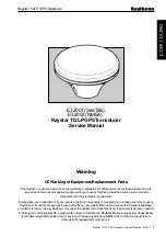
Attach the optional external GPS antenna if needed, to enhance signal when tracker installed inside the vehicle.
Connect GPS antenna to the
GPS
antenna interface to enlarge
enhance
the GPS signal while install the device
inner
inside
the vehicle. The optimum location for the GPS antenna is on the roof of the vehicle. The covert and
GPS antenna are directional, make sure they are facing up and lying as flat as possible. Secure them in place with
glue or zip ties.
Note: Do not shield or cover the GPS antenna with any objects containing metal.
7.2 Install I/O Cable
7.2.1 The Definition of I/O Cable
The I/O cable includes power, analog input, negative/positive input and output.
1
SOS GND
(Black)
3
SOS
(White)
5
Input 1
(Yellow)
7
Input 2
(Orange)
9
Input 2
(Brown)
11
Input 3
(Grey)
2
Device Input
Power
(Red)
4
Device GND
(Black)
6
Remote
Control GND
(Black)
8
Remote Control
Power (Yellow)
10
Remote
Control signal
wire (Green)
12
Analog Input
(Blue)
No.
I/O
Description
1
SOS GND
GND as input1 triggering.
2
Device Input Power
DC 9V~36V. 12V, under voltage and over voltage protection


