DR-
8000 Video Switching Matrix
-22-
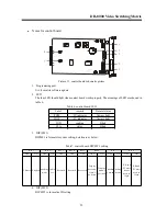
1. DIP Switch (SW1)
This is for board setting.
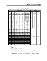
Table 12 Video output character screen overlay board DIP (SW1) setting
2. DIP (SW2)
DIP SW2 is for board ID setting
£¬
please refer to table 13 to set the ID.
Table 13 Video output character screen overlay board DIP (SW2) setting
3. LED
The four LED should be lit when Video output character screen overlay board works properly. The
meanings of LED are showed in table 14:
Table 14, Video output character screen overlay board LED
4. Programming port
It is for board software update
5. DIP (RP1)
It sets internal RS485 terminal 120
Ω
resistor. ON: connect 120
Ω
resistor, OFF: disconnect.
6. DIPs
This group of DIPs is for 16 channels video switching setting, please set them strictly according its
ID, otherwise it will cause mass switching.
BIT1
BIT2
BIT 3
remark
BIT4
BIT5
BIT6
BIT7
BIT5
OFF
OFF
OFF
Normal
status
ON
ON
/
Big font
ON
OFF
/
Small
font
ON
/
ON
English
ON
/
OFF
Chinese
OFF
reserved
initialize
BIT1
BIT2
Board ID
BIT3
BIT4
BIT5
BIT6
BIT7
BIT8
ON
ON
1
OFF
ON
2
ON
OFF
3
OFF
OFF
4
ON
reserved
Set board ID
Label
remark
Normal status
POW -
-5V indicator
Alw ays light
POW +
+5V indicator
Alw ays light
COD
sending
Blink
STA
status
Blink

