background image


b)


Connect  mains  wires  with  the  input  terminal  block  of  the  RIP,  the  F1  (2 A)  fuse 

being  preliminary  removed  from  the  terminal  block.  The 

LINE  wire  must  be 

connected to the terminal XT1/4

c)


Connect  the  load  to  the  output  terminal  block  observing  polarity  (

ХТ

2/7,8  to  «+» 

and 

ХТ

2/4,5,6  to  «

-

»).  If  several  load  devices  are  to  be  connected  then  Bolid 

manufactured BZK DC Power Modules are recommended to be used; 

Note:

  The  rated  load  current  is  3 A.  Short-term  operation  of  the  RIP  is  allowed 

once  per  hour  at  a  load  current  of  up  to  4 A  (2  min)  when  sound  alarms, 
extinguishing control units, control appliances, etc. are turned on. 

d)


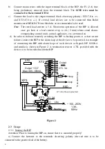
In order to indicate remotely  switching the RIP to backup power or a short circuit 

failure, connect the RIP to the alarm loop of the devices to be powered. An example 
of  connecting  the  RIP  with  alarm  loops  of  such  devices  as  Signal-20P,  S2000-4, 
and  similar  is  shown  in  Figure 2.  A  termination  resistor  4.7 K  provided  with  the 
devices is to be installed inside the RIP. 

XP2

XP3

RED

Output

27V, 3A

Line

Neutral

XT1

F1  2A

4

5

6

1

3

2

XP4

XP5

X1

X2

XT2

1

2

3

4

W1

W1 is for the wire provided

~ 150...253V,

1.3A,
50Hz

L

N

Output “+OC”

Max: 30V, 100mA

+OC

+loop

-loop

4.7K

T

o

 a

n

 a

la

rm

 l

o

o

p

5

X3

X4

6

7

8


Figure 2


2.3


Usage 

2.3.1


Starting the RIP 

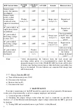
Attention! Prior to turning the RIP on, ensure that it is mounted properly! 

а

)


Connect  the  batteries  to  the  terminals  observing  polarity  (the  red  wire  is  to  be 

connected to the positive lead of the battery). 

Содержание RIP-24

Страница 1: ... GOST 15150 69 but to be used within temperature ranges of 263 К to 313 К 10 С to 40 С and ambient humidity of up to 90 at 298 К 25 С 1 1 6 In terms of mechanical tolerance the RIP corresponds to Category LX in accordance with GOST 12997 84 vibration within 1Hz to 35 Hz when accelerated up to 4 9 m s2 0 5 g 1 2 Specifications 1 2 1 The main power supply is the mains power 150 253 V 50Hz 1 2 2 The ...

Страница 2: ...ra 12 V batteries of 17 Ah each placed in a special Box 24 Mod 0 to increase the time of operation from the batteries with total capacity of all RIP batteries being equal to 2 24 Ah 1 2 16 The RIP provides immunity to electromagnetic interference of the third severity level according to Russian Standard GOST R 50009 2000 1 2 17 Radio disturbances from the RIP operation do not exceed the values spe...

Страница 3: ... third or higher safety qualification level can mount and maintain the RIP CAUTION Connecting the RIP to the mains utility power please KEEP UP the correct coupling of LINE and NEUTRAL TERMINALS in agreement with the picture located inside the cabinet closely to power terminal block 2 2 Mounting and Preparing for Operation 2 2 1 The RIP is to be installed on walls or other structures in the protec...

Страница 4: ...rder to indicate remotely switching the RIP to backup power or a short circuit failure connect the RIP to the alarm loop of the devices to be powered An example of connecting the RIP with alarm loops of such devices as Signal 20P S2000 4 and similar is shown in Figure 2 A termination resistor 4 7 K provided with the devices is to be installed inside the RIP XP2 XP3 RED Output 27V 3A Line Neutral X...

Страница 5: ...mains power supply fails the batteries begin to power the load circuit the 24 V indicator being turned on and the sounder going off periodically The POWER and CHARGE indicators are off e If the voltage of the batteries has dropped to 22 V the sounder switches on and off five to ten times more rapidly It is necessary to take measures to restore mains power line as soon as possible f If the voltage ...

Страница 6: ...arge discharge cycle Note After disconnecting the batteries from the load circuit and recovering utility power it is recommended to check the battery charge discharge cycle If the CHARGE LED has been still lit after 24 hours since having restored power then the battery operability has been to be checked If extra batteries are connected the charge time will be increased 2 3 3 How to Turn the RIP Of...

Страница 7: ...e technical support 7 495 775 71 55 or e mail support bolid ru 4 4 When submitting the product for repair it shall be accompanied with descriptions of possible fault Claims shall be submitted to the following address NVP BOLID CJSC Pionerskaya 4 Korolyov city Moscow region Russia 141070 Phone fax 495 775 71 55 multiline 516 93 72 E mail info bolid ru Support support bolid ru http bolid ru 5 CERTIF...

Страница 8: ...ts of state standards and applicable technical documentation and approved as ready for operation 6 2 Battery Backed Power Supply RIP 24 model 01 RIP 24 3 7M4 is packaged by CJSC NVP Bolid in line with the requirements provided in the current technical documentation Responsible for acceptance and packaging QCD _____________________________ ________________________ Full Name Data Month Year ...

Отзывы: