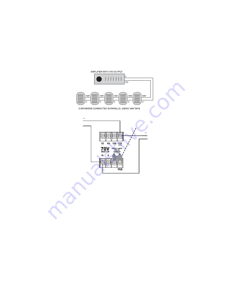
70V SYSTEM CONFIGURATION
+
+
Shown with jumper in place
To next speaker
This example uses the
1
6W tap.
In a real installation, any of the
five 70V taps (8W,
1
6W, 32W,
64W, or
1
28W) may be used.
From amp
When designing a 70V system, the total of all the power tap settings of all the
connected speakers cannot exceed the output power of the 70V amplifier. The
example below shows five speakers connected in parallel. Using the
1
6W termi-
nals, an amplifier is needed with a power rating of at least (5) × (
1
6) = 80W. A
good rule of thumb is to select an amplifier with 20% more power; in this case,
an amplifier that delivers about
1
00W.
When using multiple low-impedance speakers wired in parallel, it is important
to know the total load that these speakers present to the amplifier and to
select an amplifier that is stable into that load. The A
1
2 has a
1
6-ohm input im-
pedance which allows for easy paralleling of multiple speakers. In the example
on the next page, four speakers are paralleled on each amplifier output, so that
each run has a total impedance of 4 ohms. The amplifier is selected to be stable
into this load impedance.
LOW-IMPEDANCE SYSTEM CONFIGURATION


