background image

BOGE Operating instructions for C 10 L...C 20 L series screw compressors

Page 45

Maintenance

5.3

Regular maintenance work

Checking the safety 
valve

Check:

After approx. 3,000 operating hours, however, at least once a year.

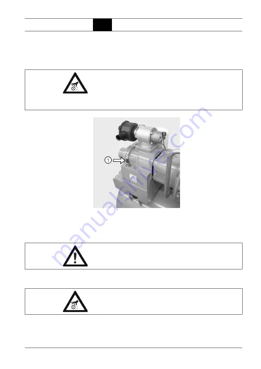
Check safety valve by opening the screw plug (1).

Fig. 5.9: Check safety valve

Nozzle with dirt catch

Change: 

After 3,000 operating hours, however, no later than after one year.

Switch off the compressor using the OFF button.

Caution: Risk of injury!

Danger of burning due to hot oil!
Take extreme care when checking the safety valve with the compressor run-
ning taking all safety measures into consideration.
Always wear safety gloves!
A hot air-oil mixture escapes when opening!

Open the threaded plug 
(1) counterclockwise. The 
air-oil mixture escapes.

Tighten the threaded plug 
by turning clockwise.

Attention!

If the prescribed maintenance intervals are not complied with, the residual oil 
content in the compressed air rises considerably.

Caution: Risk of injury!

Press Emergency Stop button, open mains disconnection device and secure 
against unintentional switch on by means of a padlock.

Содержание C 10 L

Страница 1: ...www boge com Operating instructions Directly coupled screw compressors Series C 10 L C 20 L Separate manual Compressor control ...

Страница 2: ......

Страница 3: ...or directly coupled screw compressors C 10 L 10 0 Hp C 15 L 15 0 Hp C 20 L 20 0 Hp BOGE KOMPRESSOREN Postfach 10 07 13 33507 Bielefeld Germany Otto Boge Straße 1 7 33739 Bielefeld Phone 49 5206 601 0 Fax 49 5206 601 200 Mail info boge com Net www boge com Issue 12 2011 No 596 1191 18 Nominal price 5 00 ...

Страница 4: ......

Страница 5: ...ata on the type plate 8 Service 8 Part 2 Product description 2 1 Technical data 9 2 2 Function description 10 Function principle of the air end 10 Air circuit 11 Oil circuit 12 2 3 Compressor control 13 Network pressure 13 Operating states 13 Operating modes 13 Short operating times 14 2 4 Control devices 14 Operating pressure sensor 14 2 5 Safety and monitoring devices 14 General 14 Safety valve ...

Страница 6: ...r network 23 Checking the oil level 23 3 4 Electrical connection 23 3 5 Commissioning 24 Check installation requirements 24 Checking the rotational direction 25 Check compressed air outlet for tightness 25 Opening the stop valves 26 Checking for leaks 26 Conduct trial run 26 Commissioning following extended stoppages 26 Refrigeration compressed air dryer 27 3 6 Dismantling 28 Part 4 Faults 4 1 Gen...

Страница 7: ...ng up oil 38 Changing the oil filter 39 Changing the oil separator 40 Oil change 42 Flushing the oil circuit 44 Cleaning the compressed air oil cooling unit 44 Checking the safety valve 45 Nozzle with dirt catch 45 5 4 Spare parts and optional equipment 47 List of spare and wearing parts for maintenance 47 List of available optional equipment 47 Part 6 Appendix 6 1 Flow chart 49 Air cooled version...

Страница 8: ......

Страница 9: ...Ensure that all safety claddings and doors are closed prior to commission ing starting up the compressor and that they are not opened during oper ation 7 Place the compressor out of operation as described in these operating instructions when dismantling the safety claddings or safety devices for repair or maintenance work Reattach and close all cladding and safety devices immediately upon completi...

Страница 10: ...rts and devices under current is prohibited Exceptions are governed by the appropriate regulations 7 The operator is responsible to check the compressor daily for externally visible damage and defects and to immediately report any changes including operational behaviour 8 When the automatic restart Auto Restart is activated the compressor will start automatically following a voltage loss Prerequis...

Страница 11: ...d water discharge pipework to and from the inlet and discharge port connections must be designed in such a way as to take into account vibration pulsations temperature maximum pressure applied corrosion and chemical resistance In addition it should be noted that lubricated compressors will discharge some oil into the air stream there fore compatibility between discharge piping system accessories a...

Страница 12: ...t prevention and envi ronmental protection In the illustrations the compressor is shown in part without safety cladding or safety devices for better visualization However operation without these com ponents is prohibited Symbols used In these operating instructions important safety instructions and tips are iden tified by the following symbols DANGER Risk of injury This symbol indicates informatio...

Страница 13: ...rules your health will be endangered Before putting into service read the instructions check electric connections check oil level not for oil free if applicable remove the transportation safety device check the direction of rotation of compressor operate only with a belt protective grating or a sound protection bonnet do not close the cooling air inlets and outlets during operation Regular mainten...

Страница 14: ...G High pressure air Can cause severe injury or death Relieve pressure before removing filter plugs caps fittings or covers WARNING Exposed fan blade Can cause severe injury Do not operate with covers removed Disconnect power Lock and tag WARNING NOTICE Rotation High pressure air Can cause severe injury or death Relieve pressure before removing filter plugs caps fittings or covers WARNING Hot surfa...

Страница 15: ...nt to properly filter and or purify the air to meet all applicable federal state and local laws rules regulations and codes such as but not limited to OSHA 29 CFR 1910 134 Compressed Gas Association Commodity Speci fication G 7 1 1966 Grade D Breathing Air and or Canadian Standards Association Should the Purchaser and or User fail to add such specialized equipment and proceeds to use the compresso...

Страница 16: ...days after ar rival of the delivery Data on the type plate Enter the data of your compressor from the type plate or enclosed data sheet in the illustration below This will ensure that in the event of enquiries you will always have the most important data to hand Fig 1 1 Data on the type plate Service Please do not hesitate to contact BOGE service if you have any questions Please call Telephone 1 7...

Страница 17: ...30 230 Volume flow according to ISO 1217 appendix C at pmax 115 psig cfm 69 pmax 150 psig cfm 36 77 Drive motor Rated power Hp 10 15 20 Nominal speed 60 Hz min 1 1800 3600 3600 Protection type TEFC TEFC TEFC ISO class F F F Electrical connection Mains voltage 1 V Frequency 1 Hz Recommended fuse protection 2 3 A 1 Standard equipment Mains voltages and frequencies are specified on a plate in the swi...

Страница 18: ...n in to be compressed to the final pressure in the chambers During compression oil is continuously injected into the air end This having a cooling sealing and lubricating function Type C 10 L C 15 L C 20 L Oil filling quantity Total oil filling quantity gallon 2 12 2 12 2 12 Oil topping up quantity between min max gallon 0 264 0 264 0 264 Intake air temperature min F 41 41 41 max F 104 104 104 Coo...

Страница 19: ...air oil receiver 5 Oil separator The oil separator separates the residual oil contained in the compressed air 6 Minimum pressure check valve The minimum pressure check valve does not open until the system pres sure has increased to 51 psig This causes a rapid build up of the system pressure and ensures lubrication in the starting phase Once the com pressor has been switched off the check valve pre...

Страница 20: ...out of the receiver into the air end 2 Thermostatic oil control valve Depending on the oil temperature the thermostatic oil control valve either allows the oil to pass through the oil cooler or through a bypass e g in the starting phase Thus the oil constantly maintains its optimum operating temperature 3 Oil cooler air or water cooled The oil cooler cools down the hot oil to operating temperature...

Страница 21: ...e drive motor and reduces wear of the system 3 Standstill ready for operation The compressor is standing still but ready for operation When compressed air is required it switches automatically to load operation Operating modes The two most important operating modes are achieved by combining the three operating states 1 Intermittent operation In intermittent operation the energy balance is perfect ...

Страница 22: ... guarantee a high degree of operational safety in connec tion with the BOGE monitoring system When one of the safety devices responds the control system reacts as follows The compressor is immediately switched off A flashing fault number in the left field of the display indicates the cause of the fault The following monitoring devices are standard for BOGE control systems Attention During short op...

Страница 23: ... tempera ture Rectify the fault Acknowledge fault by pressing ENTER key Switch on the compressor ON button Monitoring the drive motor The drive motor is monitored by PTC resistors The safety valve 1 on the compressed air oil receiver prevents the maximum admissible pressure being exceeded When the maximum pressure is exceeded e g incorrect setting of the operating pres sure value the entire delive...

Страница 24: ......

Страница 25: ...gear lifting cart or forklift truck must correspond at least to that of the compressor see Technical Data Mind the position of the mass centre prior to lifting the compressor The posi tion of the mass centre is specified both in the attached dimensioned drawing and on the packing of the compressor Lifting lugs on certain component parts e g electric motor are exclusively intended for lifting the i...

Страница 26: ...nsport slings having a minimum length of approx 315 inches Place loops of the transport slings at the head sides underneath the supplied trans port pallet of the compressor Neither fasten the transport slings to the suction filter nor to the eyelet on the motor Note In case of an intermediate storage please observe the specifications and directions as to permissible environmental impacts see chapt...

Страница 27: ...inst damage through mechanical effects e g falling objects Operate the compressed air receiver and its equipment from a safe loca tion Adhere to safety areas and safety clearances Ensure that the compressed air receiver stands securely It must not shift or tilt due to external forces This also includes the additional weight dur ing a pressure test The compressed air receiver must not be bolted to ...

Страница 28: ... air openings close to the floor Arrange exhaust air openings in the ceiling or at the top of the wall The required cross sections for the supply openings as well as for the flaps and weather protection grids are indicated in the table Attention Nonobservance of the admissible ambient temperature may lead to the fol lowing problems The compressor will switch off when the admissible final compressi...

Страница 29: ...ntacting a specialist company for performing the duct construction work and planning For the cooling air requirements the basis is a 39 F temperature difference between room and outside tempera ture Table 3 1 Cooling air requirement necessary aperture dimensions Condensate disposal The air taken in contains water in form of vapour which turns into condensa tion during compression Type Drive rating...

Страница 30: ...ny possible accessory equipment The delivery scope includes the following component parts Operating instructions Electric circuit diagram in the compartment of the switch cabinet List of electrical equipment in the compartment of the switch cabinet Oil drainage hose Head nut in the compartment of the switch cabinet Spare parts list Installing the compressor Remove the packing material on and in th...

Страница 31: ...f your mains operating voltage control voltage type of current fre quency must coincide with the data on the type plate on the switch cabinet In the event of deviations please contact the BOGE service or your supplier Connecting the leads Check to ensure that all terminals in the switch cabinet are firmly tight ened If necessary retighten the screw connections Guide the lead cable through the PG s...

Страница 32: ...compressor may re start automatically after a voltage failure Prerequisite The network pressure is lower than the set cut in pressure of the operating switch and it was al ready switched on before the mains failure green indicator lamp ON Note We recommend the drawing up of a commissioning certificate in which the test results during the commissioning process can be listed up Caution Risk of injur...

Страница 33: ... up the test results in the commissioning certificate Caution Ensure that the rotational direction coincides with the rotational direction ar row on the air end Switch on the main switch Switch the compressor on and immediately off again to check the rota tional direction Caution Risk of injury Switch off the main switch and secure against unintentional switching on Interchange two phases L1 L2 or...

Страница 34: ...following extended stoppages If an extended stoppage is scheduled you should contact BOGE Service beforehand Following an extended stoppage of more than 2 months fill a small amount of oil in the suction controller prior to starting the compressor Caution Risk of injury Press Emergency Stop button open mains disconnection device and secure against unintentional switch on by means of a padlock If n...

Страница 35: ...and secure against unintentional switching on Unscrew the plug on the suction controller 1 Fill approx 0 026 gallon compressor oil into the suction controller Reclose the controller using the plug Prior to switching on the compressor wait for ap prox 10 min until the oil has spread evenly Then switch the compressor on and immediately off again After approx 10 sec the compressor can be start ed Cau...

Страница 36: ...ried out by experienced and authorized qualified personnel Make also sure to observe all information in the attached operation instruc tions as to a safe dismantling of the refrigeration compressed air dryer and a secure disposal of the coolant Caution High voltage All work on the electrical installation may only be carried out by authorized and skilled electricians Prior to starting the work the ...

Страница 37: ...tions Telephone 1 770 874 1570 Telephone 49 5206 601 140 Caution High voltage Prior to any work required to rectify faults Open mains disconnection device and secure against unintentional switch on by means of a padlock Fault Possible cause Rectification No quantity delivered no pressure build up max pressure 0 5 bar System components in the com pressor are leaking Check oil and compressed air lin...

Страница 38: ... leaking Check the minimum pressure check valve and replace if necessary Suction controller is leaking Check the suction controller and replace if necessary Cut out performed by emer gency stop button Cut out normally via O key Excessive oil consumption Drain line is blocked Dismantle and clean nozzle with dirt catch Defective oil separator element Check oil separator and replace if necessary Exce...

Страница 39: ...ch on pressure Caution Risk of injury Always adhere to the prescribed operating method described below for all maintenance work Never omit a single safety step Otherwise you will risk injury from restarting electric shock or parts which may fly off Prior to all maintenance work 1 Switch off the compressor using the OFF button 2 Switch off the main switch and secure against unintentional switching ...

Страница 40: ... adjust pressure 2 Clean oil cooler 3 Top up oil in the suction controller after an extended down time 4 Check suction filter Clean Change filter cartridge 5 Change oil separator 6 Change oil filter 7 Replace nozzle with dirt catch 8 Check oil level Top up oil 9 Change oil Note Maintenance agreement Enter into a maintenance agreement with BOGE BOGE service will carry out the proper maintenance on ...

Страница 41: ...ating and ambient conditions Extreme conditions may require shorter maintenance intervals Note Note down any maintenance work in the table on the last page This will facilitate trouble shooting for BOGE service Attention Check monthly if all screw connections on the compressor are fully tight ened Please change oil and replace oil filter and nozzle with dirt catch after the first 500 operating hou...

Страница 42: ...tion filter cartridge X 37 Check safety valve X 45 Replace minimum pressure valve wearing parts set X Replace suction controller X Oil circuit Check oil level and top up as required 2 X 38 Change oil separator 2 X 40 Change oil filter 2 X 39 Change oil 2 X 42 Replace oil regulator wearing parts set X Replace nozzle with dirt catch X 45 Drive Lubricate drive motor bearings Drive motors with permane...

Страница 43: ...tection of metallic surfaces Excellent oxidation stability Rotating bomb oxidation Test ASTM D 2272 higher than 2 400 minutes Or you use BOGE compressor oil Syprem 8000 S The stated maintenance intervals refer to the use of Syprem 8000 S only Syprem 8000 S can be purchased from BOGE retailers Never mix different oil types and brands The additives may be incompatible It may lead to foam formation p...

Страница 44: ...ator cartridges require special waste treat ment and must be kept separate from normal waste Caution Risk of injury and damage to compressor due to obsolete pressure hoses Never use pressure hoses beyond the prescribed service life Check hoses and connections regularly for leakages Check the service life of the hoses and replace them in due time As replacement only use original spare parts release...

Страница 45: ...itch off the compressor with the OFF button Fig 5 2 Changing the suction filter Cleaning the filter cartridge Caution Risk of injury Press Emergency Stop button open mains disconnection device and secure against unintentional switch on by means of a padlock Removing the filter car tridge Remove lid 1 of the filter housing Remove filter cartridge 2 Attention Do not clean filter cartridges in liquid...

Страница 46: ...e maintenance free for the service life For motor maintenance see operating instructions of the compressor comtrol The service life decreases or increases as thermal stress increases or de creases due to increased or reduced coolant temperature Checking the oil level topping up oil Check Prior to commissioning start up of the compressor Then every 1 000 operating hours however at least once a year...

Страница 47: ...erating hours After 3 000 operating hours however no later than after one year With each oil change Switch off the compressor using the OFF button Caution Risk of injury Danger of burning due to hot oil Always wear safety gloves Remove plug 2 of oil fill ing socket 1 Check oil level The oil level must not drop to a level more than 0 8 inch below the bottom edge of the thread If necessary top up wi...

Страница 48: ...n screws Open ball valve at the compressed air outlet Switch on compressor and run till it reaches operating temperature Check tightness of service cover and re tighten screws Fig 5 4 Changing the oil filter Changing the oil separators Changing the oil separator Change When warning message 8 appears on the control system display FOCUS only After 3 000 operating hours however no later than after on...

Страница 49: ...aks and tighten by hand if necessary Caution Risk of injury Danger of burning due to hot oil Always wear safety gloves Remove cladding from the service side Unscrew soiled oil sepa rators 4 by hand or use a strap wrench turning counterclockwise Catch the draining oil and dispose of properly ac cording to environmental regulations Lightly oil the sealing rings of the new oil sepa rator Screw in new...

Страница 50: ...le collecting basin Switch off the compressor using the OFF button Draining old oil Fig 5 6 Solenoid valve on the suction controller with the cap nut screwed on Note The service life of the oil the oil filter and oil separators is reduced under the following conditions When the compressor is operated at extreme ambient temperatures When the intake air is extremely soiled Caution Risk of injury Pre...

Страница 51: ...eaks and tighten by hand if nec essary Check oil level procedure as described above Top up oil losses if any Remove blind plug 1 at oil drain 3 with the tap closed Fit oil drainage hose 2 The hose is located on the machine Place the oil drain hose into a suitable container Slowly open the stop valve The pressure cushion forces the oil into the container Once the compressed air oil receiver has bee...

Страница 52: ...e 1 770 874 1570 Telephone 49 5206 601 140 Note The service life of the compressed air oil cooling unit depends on the degree of soiling dust oil vapour of the suctioned cooling air Extreme external soil ing of the cooling unit leads to an increased temperature in the oil circuit Caution Risk of injury Press Emergency Stop button open mains disconnection device and secure against unintentional swi...

Страница 53: ...isk of injury Danger of burning due to hot oil Take extreme care when checking the safety valve with the compressor run ning taking all safety measures into consideration Always wear safety gloves A hot air oil mixture escapes when opening Open the threaded plug 1 counterclockwise The air oil mixture escapes Tighten the threaded plug by turning clockwise Attention If the prescribed maintenance int...

Страница 54: ...essor as described in the beginning of the chapter Wait approx 3 minutes to permit the oil to settle Screw out plug 1 and nozzle 2 Pull out dirt catcher 3 to do so take a screw e g M5 x 25 screw it into the dirt catcher and pull it out The reassembly has to be performed in the reverse order First the dirt catcher 3 and the nozzle 2 and then finally close the bore 4 with the plug 1 Fig 5 10 Nozzle ...

Страница 55: ...ssor oil Syprem 8000 S Maintenance kit consisting of oil filter oil separator suction filter cartridge gaskets nozzle with dirt catch Wearing part kits for oil regulator minimum pressure valve solenoid valve Intake regulator incl solenoid valve Designation Optional equipment for compressed air treatment Oil water separator Automatic condensate draining unit Bekomat Attention When ordering please s...

Страница 56: ......

Страница 57: ...instructions for C 10 L C 20 L series screw compressors Page 49 Appendix 6 1 Flow chart Part 6 Appendix 6 1 Flow chart On the following page you will find the individual flow chart for your machine type and components ...

Страница 58: ...Appendix 6 1 Flow chart Page 50 BOGE Operating instructions for C 10 L C 20 L series screw compressors Air cooled version standard ...

Страница 59: ...l compression temperature display and switch 10 Combined compressed air oil receiver 11 Oil separator 12 Safety valve 15 Compressed air after cooler Optionally for receiver systems without refrigeration compressed air dryer 16 Thermostatic oil control valve 17 Oil cooler 18 Oil filter 21 Minimum pressure check valve 23 Network pressure transmitter 24 Pressure gauge reading in display 25 Stop valve...

Страница 60: ...List of maintenance and service work Please note the completed maintenance work in the respective columns Remarks Com pressed air dryer Motor mainte nance Cooling unit cleaning Oil separator Oil level Oil filter Intake filter Tempe rature System pressure Co Control Ch Change Network pressure Operating hours Cl Cleaning Ch Change Date ...

Страница 61: ...nd service work Please note the completed maintenance work in the respective columns Remarks Com pressed air dryer Motor mainte nance Cooling unit cleaning Oil separator Oil level Oil filter Intake filter Tempe rature System pressure Co Control Ch Change Network pressure Operating hours Cl Cleaning Ch Change Date ...

Страница 62: ...rew compressors Please note the completed maintenance work in the respective columns Remarks Com pressed air dryer Motor mainte nance Cooling unit cleaning Oil separator Oil level Oil filter Intake filter Tempe rature System pressure Co Control Ch Change Network pressure Operating hours Cl Cleaning Ch Change Date ...

Отзывы: