background image

6

Model

Accessories

Replacement Batteries

Installation Kit

Battery Harnesses

Fuse

Part No.

Quantity

ELI-S-250 & 185

PRT00143

PRT00144

Littlefuse 0312030

PRT00141

1 Required

Battery Maintenance: 

The batteries supplied with this equipment require no maintenance. However, the inverter should be 

tested periodically, and batteries replaced whenever they will no longer operate the connected fixtures for the rated run-
time. The batteries supplied have a life expectancy of four years when used in normal ambient temperature of 72 degrees F.

Battery Date Code:  The battery date code is made up of six characters which represent the month, day and year of manufacture (MM/
DD/YY). For example, 080221 means the battery was made August 2, 2021. There may be additional alpha-numeric characters at the 
end of the date code.  The date code is located on the battery carton and additionally engraved into the battery.

Battery Replacement: 

When replacing batteries, use only batteries supplied by the inverter manufacturer. The old batteries 

should be disposed of properly or recycled in accordance with your local regulations. When replacing the batteries, follow 
the process outlined in Installation Step #4 and #5 and the cautions and warnings given in these instructions.  During 
replacement, disable SW-1 on the inverter, then remove AC power from the product.

Fuse:

 The fuse contained within this product is field replaceable. For the battery fuse location see illustration 1. To replace 

the fuse, disable SW-1 on the inverter then, remove AC power from the product. Ensure that the battery fuse F101 is replaced 
by Littelfuse 0312030 (312-030) or equivalent 3AG, 30 A, 32 VDC.

REPLACEMENT PARTS

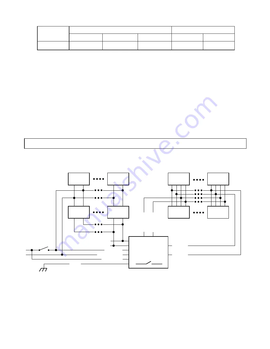
WIRING DIAGRAM

DIMMABLE EMERGENCY LIGHTING SYSTEM

Normal only

Luminaire

Normal only

Luminaire

Normal only

Luminaire

Normal only

Luminaire

Norm/Emer

Luminaire

Norm/Emer

Luminaire

Norm/Emer

Luminaire

Norm/Emer

Luminaire

120 or 277 VAC

Out HOT

Out COM

DIM OUT


+

DIM OUT


-

120 or 277 VAC

Wall Switch

INVERTER

SW-1

Inverter ON / OFF

FGND

UNSW HOT

COM (Neutral)

SW HOT

{

TOTAL DIMMABLE POWER

UP TO 800W

From 0 - 10V

Room Dimmer

DIM IN 

+

DIM IN 

-

ANY QUANTITY SUPPORTED BY

THE BRANCH CIRCUIT

FIGURE W1

Figure W1

 shows an example of a branch circuit powering a number of dimmable luminaires, 4 (or more) of which 

are powered through the Emergency Lighting Inverter. During normal AC power mode, the power from the switched 
hot lighting power and 0-10V room-dimmer voltage is passed through the Inverter to the “Normal/Emergency” 
fixtures. The 

un

switched hot charges the battery. During a power failure, the Inverter powers the “Normal/

Emergency” fixtures for a minimum of the products rated runtime at a power level set by the Inverter’s dimming 
output circuit. In any example, the 

dimmable

 “Normal/Emergency” luminaires are automatically limited to 

only


draw a total maximum of 250 VA from the ELI-S-250 during an emergency event.

Содержание ELI Series

Страница 1: ...operated in a commer cial environment This equipment generates uses and can radiate radio frequency energy and if not installed and used in accordance with the instruction manual may cause harmful interference to radio communications Operation of this equipment in a residential area is likely to cause harmful interference in which case the user will be required to correct the interference at his o...

Страница 2: ...ll likely reduce the maximum connected load to something less than 800W As a typical rule of thumb provide at least 10 margin whenever the load specifics are not well known INSTALLATION Illustration 1 below shows the inverter s main circuit board This circuit board contains the enable switch fuse and wir ing terminals Approximate locations of these items are given in Illustration 1 along with deta...

Страница 3: ...ge requirements match the output ratings of this product or damage to the load devices may occur CAUTION STEP 2 BATTERY INSTALLATION AND CABLE CONNECTION This product is provided with two sealed lead acid batteries Only the batteries supplied by the inverter manufacturer should be used Install the batteries as shown referring to Illustrations 2A and 2B With the unit secured to the mounting surface...

Страница 4: ...gency mode power into the connected load s This is referred to as Auto Dimming When AC power is restored the ELI S 250 ELI S 185 returns to normal charging mode The ELI S 250 operates the emergency lighting load for a minimum of 90 minutes The ELI S 185 operates the emergency lighting load for a minimum of 120 minutes NOTE Driver efficiency and power factor typically fall as dimming level decrease...

Страница 5: ...est Switch Two Times Manually initiates a 30 second diagnostic test The inverter will switch to the emergency mode for 30 seconds and test all relevant functions Once complete the inverter returns to normal AC mode and indicate any faults if detected Commissioning Test Press and Release the Test Switch Three Times Initiates a 30 second commissioning test The inverter will switch to the emergency m...

Страница 6: ...duct Fuse The fuse contained within this product is field replaceable For the battery fuse location see illustration 1 To replace the fuse disable SW 1 on the inverter then remove AC power from the product Ensure that the battery fuse F101 is replaced by Littelfuse 0312030 312 030 or equivalent 3AG 30 A 32 VDC REPLACEMENT PARTS WIRING DIAGRAM DIMMABLE EMERGENCY LIGHTING SYSTEM Normal only Luminair...

Страница 7: ... maximum output power FIGURE W2 7 Normal only Luminaire Normal only Luminaire Normal only Luminaire Normal only Luminaire Norm Emer Luminaire Norm Emer Luminaire Norm Emer Luminaire Norm Emer Luminaire 120 or 277 VAC Out HOT Out COM 120 or 277 VAC Wall Switch SW 1 Inverter ON OFF FGND UNSW HOT COM Neutral SW HOT TOTAL POWER 250W INVERTER ANY QUANTITY SUPPORTED BY THE BRANCH CIRCUIT Non DIMMABLE EM...

Отзывы: