background image

Installation and startup

Operating manual 

(Serial number) 

Page 17 of 27

Lift 240 

6.2 Startup 

Switch the device on with the red toggle switch. The blue and red 
LED flash very quickly.  

Now press the bottom or top button of the remote control for about 
3 seconds until the blue LED on the top or the red LED on the bottom 
flashes more slowly.  
Now you can traverse the lift platform by pressing the remote control 
with the top button for up (UP) and with the lower knob for down 
(DOWN).  

6.3 

Coordination for the radio frequency  

Are each lift table must be adjusted for the signal detection of the 
radio frequency of the remote control.  

For teaching, the upper or the lower button of the remote control
must be pressed sequentially for 3 seconds when the lift table is
switched on.

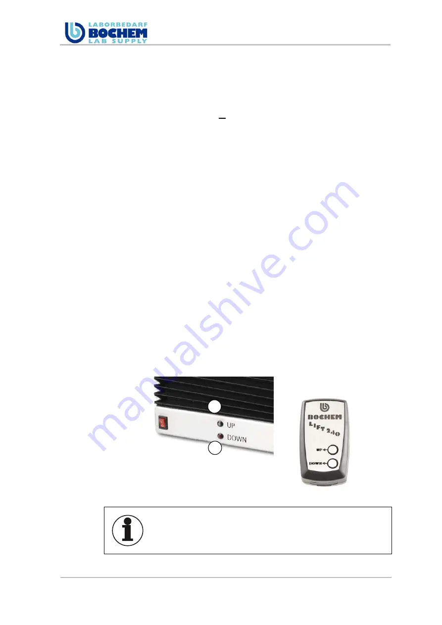
The blue (1) or red (2) LED at the base of the lift table flashes during 
the teach-in in quick succession.  
If the motor controller has detected the appropriate signal, the blue 
and red LED flash more slowly. The unit is operational.  

Lift and lower the lift table for a trial without a load.

The lift table moves until the upper or lower button of the remote 
control is pressed or until the maximum or minimum position is 
reached. A brief, inadvertent contact with the control buttons has no 
effect. 

Note 

When operating several lift tables, it is recommended to number 
the individual lift tables, for example, with labels to prevent any 
mix-ups and therefore accidents.

1

2

Содержание Lift 240

Страница 1: ... LABORBEDA BOCHEN LAB SUPPLY BOCHEM lnstrumente GmbH lndustriestraBe 3 D 35779 Weilburg Lahn Operating manual Lift 240 Save for future use ...

Страница 2: ...ation is the property of BOCHEM lnstrumente GmbH It may not be distributed or copied as photocopy recording video print or microfilm in any form without approval of the management This applies especially for the dissemination of data in electronic form or as a data medium For damages to the company caused by disregard the company retains all rights This operating manual is the property of BOCHEM l...

Страница 3: ...rements due diligence 10 2 6 1 General information 10 2 6 2 Due diligence 11 2 6 3 Training 11 2 7 In an emergency 11 3 Specifications 12 4 Machine description 13 4 1 Function description 14 5 Transport 15 6 Installation and startup 16 6 1 Assembly 16 6 1 1 Safety instructions for the installation 16 6 1 2 Procedure 16 6 2 Startup 17 6 3 Coordination for the radio frequency 17 6 4 Setting the end ...

Страница 4: ... 4 of 27 Lift 240 10 Dismantling and disposal 24 10 1 Removal 24 10 2 Storage 24 10 3 Disposal 24 11 Annex 26 11 1 Applicable documents 26 12 Warranty deed 27 Figures Figure 1 Delivery scope 5 Figure 2 View 13 Figure 3 Setting the end stop 18 ...

Страница 5: ...te GmbH Technical changes based on new research and technologies are made without prior notice Subsequent changes by the operator are not the responsibility of the manufacturer Warranty The warranty is governed by the laws of the Federal Republic of Germany The delivery scope includes Figure 1 Delivery scope Electric hoist Lift 240 Wireless remote control Power supply Operating manual Replacement ...

Страница 6: ...e must not be used in hazardous areas 2 2 Safety signs 2 2 1 Structure of safety information The following signal words are used in this document in conjunction with safety signs to illustrate possible dangers Danger Death or serious bodily injuries will occur if the respective precautionary measures are not taken Warning Death or serious bodily injuries can occur if the respective precautionary m...

Страница 7: ...hite Prohibition Safety color yellow Contrast color black Warning Safety color blue Contrast color white Order 2 2 3 Icons used in the document Icon Importance Icon Importance Warning of a hazardous area or situation Warning against a tripping risk Warning against dangerous electrical voltage Warning against hand injuries Disconnect prior to performing work Do not touch live parts Information for ...

Страница 8: ...nual Danger Danger to life by touching live parts Work on the electrical equipment must only be carried out by authorized trained personnel Faulty connections or settings can result in damages The device may only be operated with the supplied cables and wires Do not perform work on energized parts Replace damaged cables immediately Attach loose connections Carry out work only after disconnecting t...

Страница 9: ...the manufacturer Warning Risk of tripping Make sure that no loose cables or objects are located on the floor in the work area Place the device and the connections so that no one steps on it or drives or stumbles over it Attention Material and functional damage The device may not be doused with liquids sprayed with water or be exposed to rain Verify the stability when transporting and at the initia...

Страница 10: ...ry powered wireless remote control Flare signals as a status indicator Safety instructions on the device and in the operating instructions 2 5 Residual risks The rated loads of max 25 kg may not be exceeded Note Observe all warnings and safety instructions other markings such as transportation devices attached o the device 2 6 Staff requirements due diligence 2 6 1 General information Never allow ...

Страница 11: ...liable and trained personnel Maintenance work may be performed by professionals who due to their specialized training knowledge experience and knowledge of the relevant provisions assess the work assigned to them identify potential hazards and can take necessary measures to reduce accident hazards 2 7 In an emergency Note the following points Locations of first aid stations must be known Personnel...

Страница 12: ... mm min Traversing distance of scissors max 180 mm Load capacity max 25 kg Motor data Rated torque 5 Nm Idle speed 70 rpm Tightening torque 56 Nm Transmission ratio 69 1 Protection type IP 24 Energy supply Power consumption 12 000 mA Supply voltage of transformer 100 240 VAC 50 60 Hz Power output 24 V Battery remote control 3 V lithium cell CR2430 Environmental conditions Approved ambient temperat...

Страница 13: ...achine description Figure 2 View Item Designation 1 Lift platform 2 Bellows covers electric motor and lift mechanics 3 Base 4 ON OFF switch 5 LED ready UP DOWN 6 Knurled nut adjustable end stop 7 AC adapter connector on the back 8 Power supply 9 Remote control 4 1 5 2 3 6 8 9 7 ...

Страница 14: ...device is powered by a 24V electric motor with worm gear A laboratory unit placed on the lifting platform can be continuously lifted by remote control or lowered The maximum lifting height may be limited by an adjusting wheel fixation see Section 0 The remote control allows the of operating multiple lift tables via a display selection Each lift table must first be taught to its control frequency s...

Страница 15: ...lift table during transport by the lifting platform or bellows The bellows could be damaged Hold the lift table by the base during transport Attention Material damage and risk of injuries Work carefully hands and feet can be crushed When transporting the lift table secure it against falling and crashing Secure loose equipment parts before transporting against falling ...

Страница 16: ... Watch for good ergonomics Make sure that no cables are pinched Warning Risk of tripping Make sure that no loose cables or objects are located on the floor in the work area Place the device and the connections so that no one steps on it or drives or stumbles over it 6 1 2 Procedure Select a suitable location Power supply Connect the power supply with the lift table 1 Connection pos 2 Plug the powe...

Страница 17: ...ote control For teaching the upper or the lower button of the remote control must be pressed sequentially for 3 seconds when the lift table is switched on The blue 1 or red 2 LED at the base of the lift table flashes during the teach in in quick succession If the motor controller has detected the appropriate signal the blue and red LED flash more slowly The unit is operational Lift and lower the l...

Страница 18: ...top in direction the maximum height of the lift platform is reached Shifting in direction limits the height You need a measuring tape or yardstick to determine the upper endpoint Raise the loaded lift platform by pressing the blue button on the remote control until the desired height is reached Is the desired height is reached shift the slide until it audibly snaps into place Now tighten the thumb...

Страница 19: ... lift table cannot be used in areas at risk of explosions Warning Risk of injuries by smashing laboratory equipment and released chemicals material and functional damage Observe the correct adjustment of the height limit Keep the lift table in view during the process Warning Risk of crushing and shearing the hands between the lift table scissors Do not operate the lift table without bellows replac...

Страница 20: ...p UP or down DOWN for about 3 seconds the unit is then ready Raising the lift table continue to press the button for up labeled UP on the remote control as long as you keep pressing the lift table moves upward and the LED on the unit flashes blue Lowering the lift table continue to press the button for down labeled DOWN on the remote control as long as you keep pressing the lift table moves downwa...

Страница 21: ...on the unit can be located and remedied Problem Possible cause Solution Power supply power plug not connected Connect the power plug Remote control not functioning Replace the battery of the remote control Radio signal is not detected Teach in the receiver of the control unit Defective motor Please contact our service department Lift table switched on no function ...

Страница 22: ...bles may not be pinched or crimped Cables must be routed so that they will not form tripping hazards or can be damaged Warning Risk of crushing the hands between the lift table scissors Do not operate the lift table without bellows replace defective bellows contact the manufacturer Please contact our technical service personnel when the power cable is frayed or the plug the power supply unit is da...

Страница 23: ...er storage periods the 3 V lithium knob cell CR2430 may have to be replaced The battery must be replaced at least after 6 months Fig 1 Fig 2 Push cover forward to open Remove the cover Fig 3 Fig 4 Push the battery out Insert a new battery Fig 1 Push the cover on the back of the remote control forward at a light pressure Fig 2 Remove the cover Fig 3 Push the battery out with a pointed object Fig 4 ...

Страница 24: ...nergy supply and other supply connections 10 2 Storage Store the device and components dry and protected from the elements If the storage conditions are not met components may corrode or age prematurely The service life of the device is reduced 10 3 Disposal Information Protect the environment Handling and disposal of old parts are subject to legal regulations ...

Страница 25: ...995 Safety of Machinery Prevention of unexpected restarting A1 2008 EN 1570 1998 Safety requirements for lift tables A2 2009 EN ISO 12100 2011 3 General design principles risk assessment and risk reduction EN 60204 1 2006 Safety of Machinery Electrical equipment of machines part 1 General requirement EN 61000 6 2 2005 Electromagnetic compatibility EMC Part 6 2 Generic Standards Interference resist...

Страница 26: ...E Declaration of Conformity Lift 240 DEKRA DME EMC Test Report for remote control TT200 at 869 5 MHz EMC Laboratory ELAP Belgium Instructions Cleaning of laboratory equipment of corrosion and acid resistant steels Bochem laboratory needs List Chemical resistance of laboratory steels Bochem laboratory needs ...

Страница 27: ...the manufacturer prior to shipment We grant you from the time of the purchase date 1 year warranty Damages caused by natural disasters or improper use by the customer are excluded from this warranty Please complete the following table by using the invoice Product Lift 240 Type Electric lift table Series No XXXXXXXX Date 14 06 2012 ...

Отзывы: