


15
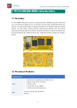
Customize the embedded system based on
Your
Idea
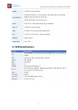
RS485
Compatible 9-bit data format, 3-pin connector (P3)
Buttons
Reset (SW2), Power (SW3), Boot Mode (SW4)
Expand interface
2x I2C, 1x SPI, 6x GPIO, 26-pin header (J11)
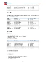
PCIe
Support USB2.0, PCIE2.1, UIM interface for SSD or 4G module
Camera
MIPI-CSI, 4 data lanes, 26-pin header (CON1)
WiFi&Bluetooth
802.11b/g/n WiFi, Bluetooth 4.0. AP6236 chipset
SIM
Nano SIM
Dimension
102.3mm x 118.6mm
2
Peripheral Introduction
Some pins are multifunctional. Pin function selection is controlled by software. Each pin can be used for
a single function at a time.
eg.
SAI1_RXFS
The default pin is
Pin39
, and
Pin43
(default function
SAI1_RXD5
) also can be used for
SAI1_RXFS
.
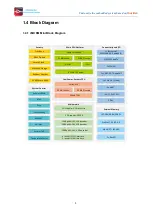
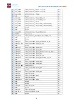
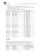
2.1 Display
MIPI DSI Features
⚫
4- lane MIPI-DSI up to 1920 x 1080 @ 60Hz
⚫
Touchscreen capacitive touch-screen support through I2C interfaces
⚫
Up to a maximum bit rate of 1.5 Gbps.
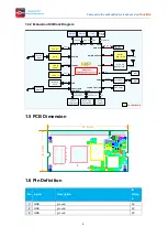
Signal
Description
Pin
Defaults Function
DSI_DP0
MIPI-DSI data0 diff-pair Positive
163
DSI_DP0
DSI_DN0
MIPI-DSI data0 diff-pair Negative
165
DSI_DN0
DSI_DP1
MIPI-DSI data1 diff-pair Positive
157
DSI_DP1
DSI_DN1
MIPI-DSI data1 diff-pair Negative
159
DSI_DN1
DSI_DP2
MIPI-DSI data2 diff-pair Positive
145
DSI_DP2
DSI_DN2
MIPI-DSI data2 diff-pair Negative
147
DSI_DN2
DSI_DP3
MIPI-DSI data3 diff-pair Positive
139
DSI_DP3
DSI_DN3
MIPI-DSI data3 diff-pair Negative
141
DSI_DN3
DSI_CKP
MIPI-DSI clock diff-pair Positive
151
DSI_CKP
DSI_CKN
MIPI-DSI clock diff-pair Negative
153
DSI_CKN
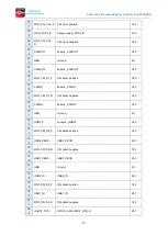
2.2 Camera I/F
⚫
Configurable interface logic to support most commonly available CMOS sensors


